
Systems and methods to provide communication and monitoring of user status

a technology of user status and system, applied in the field of systems and methods to provide communication and monitoring of user status, can solve the problems of increasing the diffusion of medical information and becoming more difficult to access, and achieve the effects of reducing paperwork, eliminating redundant data entry, and increasing responsiveness to medical situations

Inactive Publication Date: 2014-03-20
SOUNDMED LLC
View PDF7 Cites 88 Cited by
  • Summary
  • Abstract
  • Description
  • Claims
  • Application Information

AI Technical Summary

Benefits of technology

The patent describes a system that reduces paper work, collects more complete patient information, and eliminates redundant data entry. It increases responsiveness to medical situations and ensures that all patient episodes are captured and recorded. It is also a multi-purpose medical platform that is highly secure and allows healthcare providers to access previously unavailable information. The system provides real-time visibility of readiness status and support for medical command and control, telemedicine, and medical informatics applications. It can automatically inflate protective jackets and helmets to protect users from blasts or explosions and also has tamper-proof electronics to prevent unauthorized access. Overall, the system provides a standard of care to our soldiers and allows medical professionals to capture patient episodes anywhere, anytime, and ensure complete patient information is recorded and transferred to their medical record back home.

Problems solved by technology

These 60 disparate systems, while useful, resulted in an even greater diffusion of medical information, which became more difficult to access with each passing year.

Method used


Image

  • Systems and methods to provide communication and monitoring of user status
  • Systems and methods to provide communication and monitoring of user status
  • Systems and methods to provide communication and monitoring of user status

Examples


Embodiment Construction

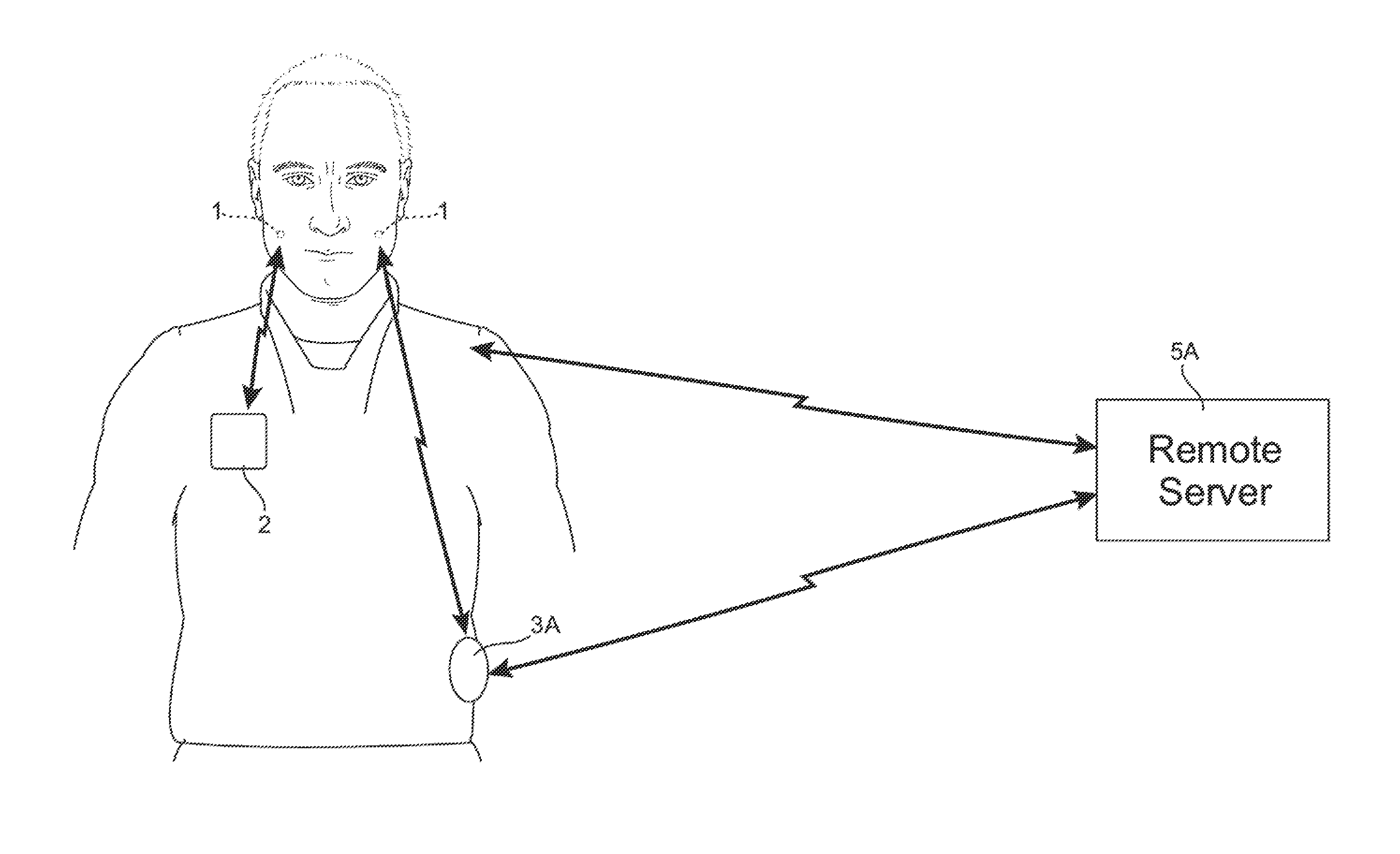
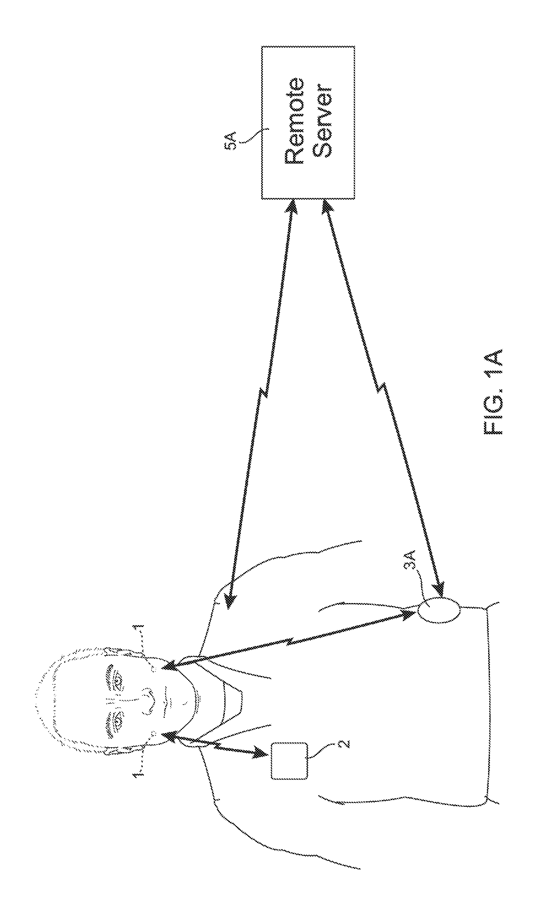
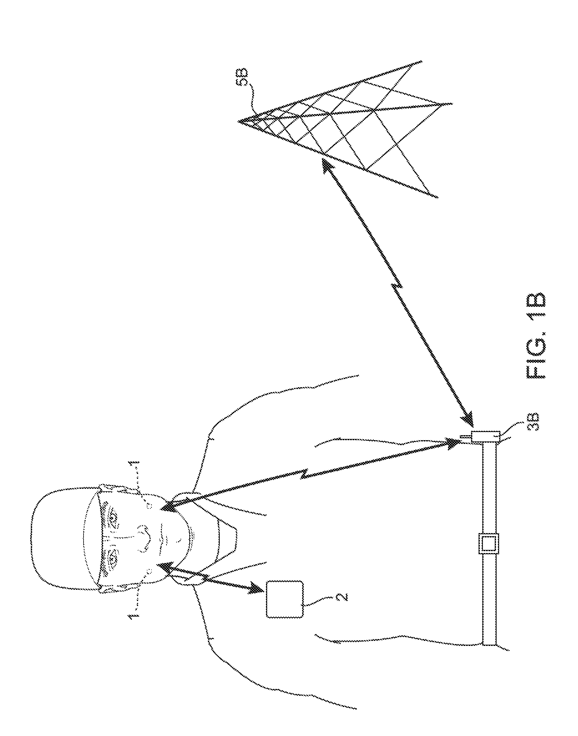
[0047]As shown in FIG. 1A, an exemplary two way communication device and / or monitoring device 1 is shown. In one embodiment, the device 1 provides an electronic and transducer device that can be attached, adhered, or otherwise embedded into or upon an intraoral appliance / device or a removable oral appliance / device to form a two-way communication assembly. The appliance or device 1 can be used by emergency personnel, medical personnel, soldiers, or any one working in a high noise environment, among others.

[0048]In the embodiment of FIG. 1A, the device 1 is mounted in the user's mouth. More details on the intraoral device 1 are discussed below. The device 1 can communicate with one or more body mounted sensors 2 through a short range personal area network. (PAN). The device 1 can also communicate with an attention device 4 such as a flashing light, among others. In case of an emergency with poor visibility, the attention device 4 can be activated to identify the wearer so that assista...


PUM


Abstract

An electronic and transducer device can be attached, adhered, or otherwise embedded into or upon a removable oral appliance or other oral device to form a two-way communication assembly. The device contains a motion sensor to detect external forces imposed on the user such as an explosion, for example. The information is stored for medical treatment, among others. In another embodiment, the device provides an electronic and transducer device that can be attached, adhered, or otherwise embedded into or upon a removable oral appliance or other oral device to form a medical tag containing patient identifiable information. Such an oral appliance may be a custom-made device fabricated from a thermal forming process utilizing a replicate model of a dental structure obtained by conventional dental impression methods. The electronic and transducer assembly may receive incoming sounds either directly or through a receiver to process and amplify the signals and transmit the processed sounds via a vibrating transducer element coupled to a tooth or other bone structure, such as the maxillary, mandibular, or palatine bone structure.

Description

CROSS-REFERENCE TO RELATED APPLICATIONS[0001]This application is a continuation of U.S. patent application Ser. No. 13 / 208,588 filed Aug. 12, 2011, which is a continuation of U.S. patent application Ser. No. 12 / 041,100 filed Mar. 3, 2008 (now U.S. Pat. No. 8,023,676), each of which is incorporated herein by reference in its entirety.BACKGROUND OF THE INVENTION[0002]Millions of living Americans are serving, or have served, the nation in the armed services. Indeed, so many Americans have passed through military service that the Department of Defense (DoD) and individual branches of the armed forces has developed more than 60 separate clinical information systems since 1980 in an effort to keep track. These 60 disparate systems, while useful, resulted in an even greater diffusion of medical information, which became more difficult to access with each passing year. Therefore, the DoD was faced with the need for a “system of systems”—a comprehensive methodology that could meet the needs ...

Claims


Application Information

Patent Timeline
Patent Type & Authority Applications(United States)
IPC IPC(8): A61B5/00A61B5/0402A61C7/08A61B7/04A63B71/08A61B5/024A61B5/08
CPCA61B5/682A61B5/0022A61B5/02438A61B5/0402A61B5/0816A61B5/7455A63B71/085A61C7/08A61B5/0006A61B5/72A61B7/04A61B5/0028A61B5/11A61B5/1112A61B5/1117A61B5/4547A61B2562/0219A61B2503/20B33Y80/00
Inventor ABOLFATHI, AMIR A.SPIRIDIGLIOZZI, JOHN
Owner SOUNDMED LLC
Learn More