Wear plate assembly

a technology of wear plate and wear plate, which is applied in the direction of drags, mechanical equipment, soil shifting machines/dredgers, etc., can solve the problems of heavy machinery parts that are expensive and time-consuming to repair or replace, and require significant time and effort, so as to prevent relative movement of the base

Active Publication Date: 2012-12-25
LOMBARDO GAETANO +1
View PDF38 Cites 13 Cited by
  • Summary
  • Abstract
  • Description
  • Claims
  • Application Information

AI Technical Summary

Problems solved by technology

The parts of heavy machines used for digging are exposed to a great amount of wear in operation.
Heavy machinery parts are expensive and time-consuming to repair or replace.
This requires significant time and effort.
However, many of these elements are welded or bolted on to the surface of the machinery part and can be difficult to replace once worn through.
In wear elements which have bases and attachable wear plates, when the abrasive wear plate is worn, the engagement means securing the base to the surface is often also damaged, which requires that the entire base be ground or cut off and replaced.

Method used


Image

  • Wear plate assembly
  • Wear plate assembly
  • Wear plate assembly

Examples


Embodiment Construction

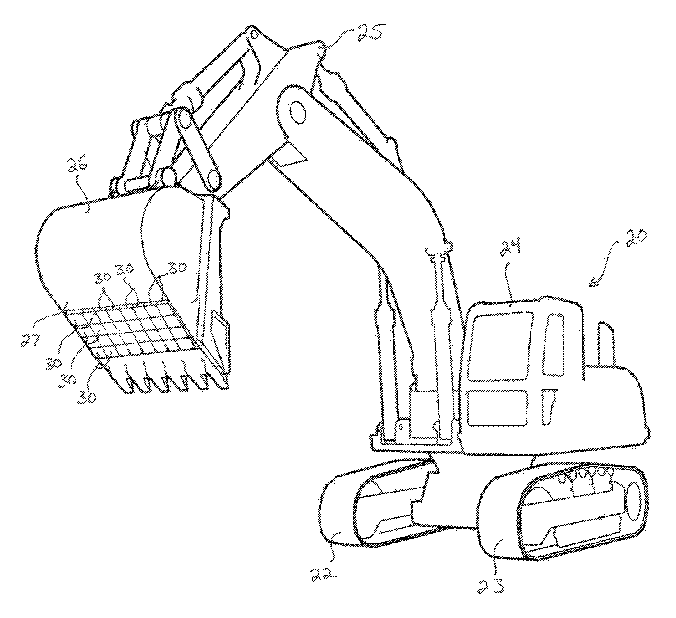
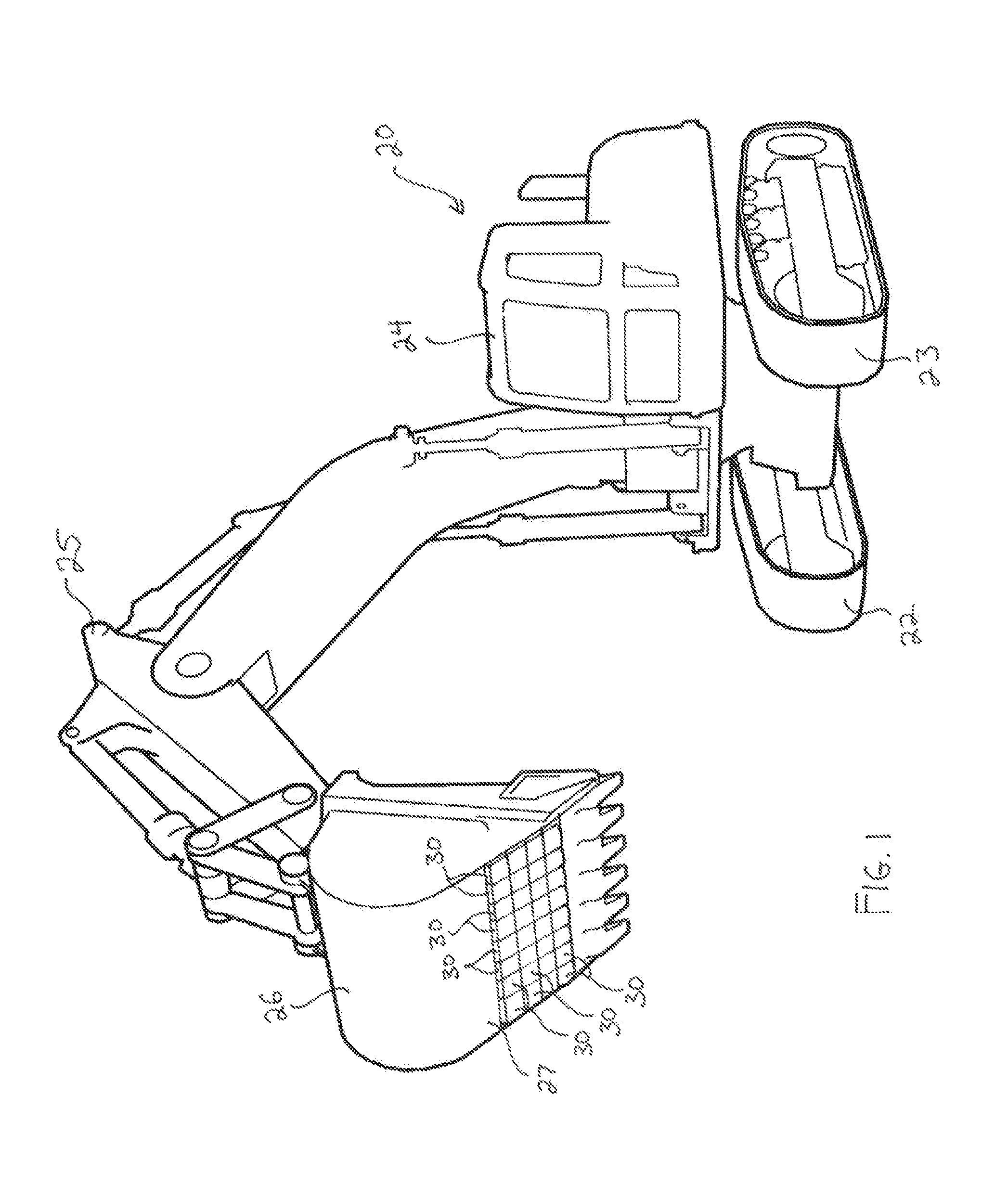
[0022]Reference now is made to the drawings, in which the same reference numbers are used throughout the different figures to designate the same components. FIG. 1 shows an excavator 20 typical of heavy machinery used for digging, ripping, crushing, cutting, lifting, or various other construction and demolition practices. The excavator 20 includes a chassis 21, two belted tracks 22 and 23 mounted to the chassis 21, an operator's cab 24, a pneumatic boom and arm assembly 25, and a bucket 26 disposed at the end of the boom and arm assembly 25. The bucket 26 has an outer surface 27 and is constructed from a strong, rigid, rugged material or combination of materials such as steel, iron, or the like. Wear plate assemblies 30 are mounted across the outer surface 27 of the bucket 26 to protect the outer surface from abrasion as the bucket 26 is ripped through the ground. The wear plate assemblies 30 are arranged in a dense array across the outer surface 27, with each wear plate assembly 30...


PUM


Abstract

A wear plate assembly includes a base, a wear plate, and a key. The wear plate is moveable with respect to the base between free and applied conditions. In the applied condition of the wear plate, the base and the wear plate cooperate to form a keyway for receiving the key. The keyway is located below the top of the base. The key is moveable between a first position corresponding to an unlocked configuration of the wear plate assembly and second position corresponding to a locked configuration of the wear plate assembly.

Description

FIELD OF THE INVENTION[0001]The present invention relates generally to heavy machinery equipment, and more particularly to wear plates for preventing abrasion of heavy machinery parts.BACKGROUND OF THE INVENTION[0002]Heavy machinery equipment are used in excavation, demolition, construction, and similar activities. The parts of heavy machines used for digging are exposed to a great amount of wear in operation. For instance, the bucket of an excavator can be used to dig, rip, crush, cut, or lift dirt, rock, concrete, metal, or other rugged materials, which constantly wear against and abrade the surface of the excavator's bucket.[0003]Heavy machinery parts are expensive and time-consuming to repair or replace. To replace a worn bucket on an excavator, for example, a new bucket must be ordered and shipped, the excavator must be taken out of operation, the old bucket must be removed, and the new one must be installed. This requires significant time and effort. Various attempts have been...

Claims


Application Information

Patent Timeline
Patent Type & Authority Patents(United States)
IPC IPC(8): E02F9/28
CPCE02F9/2883F16B3/00F16B21/02
Inventor LOMBARDO, GAETANOLOMBARDO, PASQUALE
Owner LOMBARDO GAETANO
Why Eureka
Try Eureka