Anti-rotation system for strap dispenser outer flange

a technology of anti-rotation system and outer flange, which is applied in the field of anti-rotation system of outer flange, can solve the problems of limited angle, coil and outer flange to continue to rotate,

Active Publication Date: 2012-12-25
SIGNODE IND GRP
View PDF8 Cites 0 Cited by
  • Summary
  • Abstract
  • Description
  • Claims
  • Application Information

AI Technical Summary

Benefits of technology

[0008]An anti-rotation system for a dispenser that dispenses flexible material from a coil that rotates on a dispenser shaft includes an anti-rotation element fixedly mounted to the shaft, and an outer flange mounted to the anti-rotation element. The anti-rotation element and the outer flange have complementary mating surfaces engaged with one another such that when the shaft ceases rotation, the anti-rotation element, engaged with the outer flange, ceases rotation of the outer flange; thus, rotation of the coil cannot force the outer flange to rotate undesirably.
[0012]A strap dispenser with an anti-rotation system for dispensing flexible material from a coil, includes the anti-rotation system described above, wherein the strap dispenser includes a shaft on which the coil rotates, an anti-rotation element fixedly mounted to the shaft, and an outer flange mounted to the anti-rotation element. The anti-rotation element and the outer flange having complementary mating surfaces engaged with one another such that, as discussed above, when the shaft ceases rotation, the anti-rotation element, engaged with the outer flange, ceases rotation of the outer flange of the strap dispenser, thus preventing undesired rotation of the flange by action of a rotating coil on the outer flange.

Problems solved by technology

However, when a brake is applied and the shaft stops, inertia may induce the coil and outer flange to continue to rotate.
While these configurations function acceptably, there are a limited number of angles at which the outer flange can be installed onto the dispenser.

Method used


Image

  • Anti-rotation system for strap dispenser outer flange
  • Anti-rotation system for strap dispenser outer flange
  • Anti-rotation system for strap dispenser outer flange

Examples


Embodiment Construction

[0022]While the present invention is susceptible of embodiment in various forms, there is shown in the drawings and will hereinafter be described a presently preferred embodiment with the understanding that the present disclosure is to be considered an exemplification of the invention and is not intended to limit the invention to the specific embodiment illustrated.

[0023]It should be further understood that the title of this section of this specification, namely, “Detailed Description Of The Invention”, relates to a requirement of the United States Patent Office, and does not imply, nor should be inferred to limit the subject matter disclosed herein.

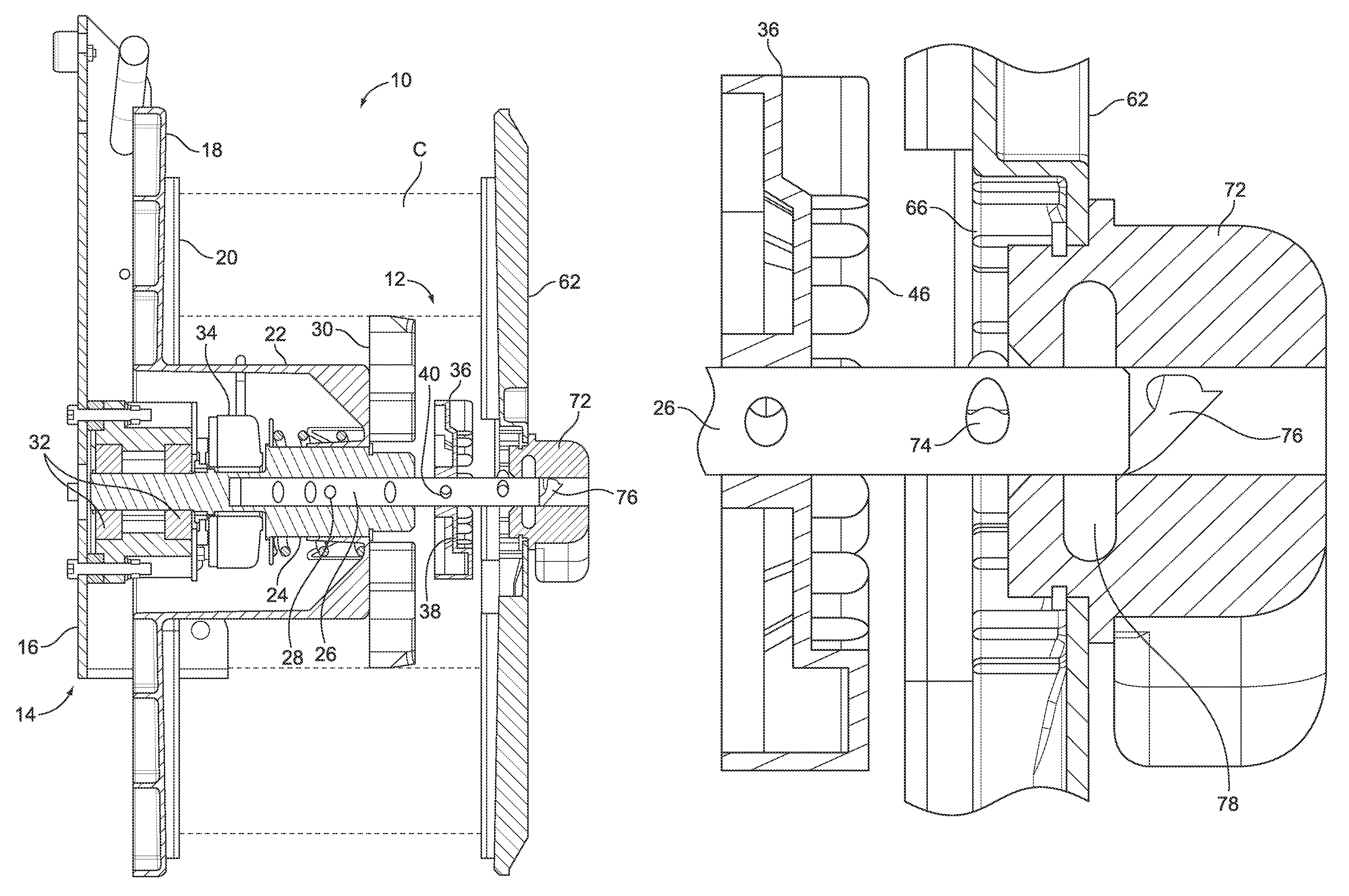
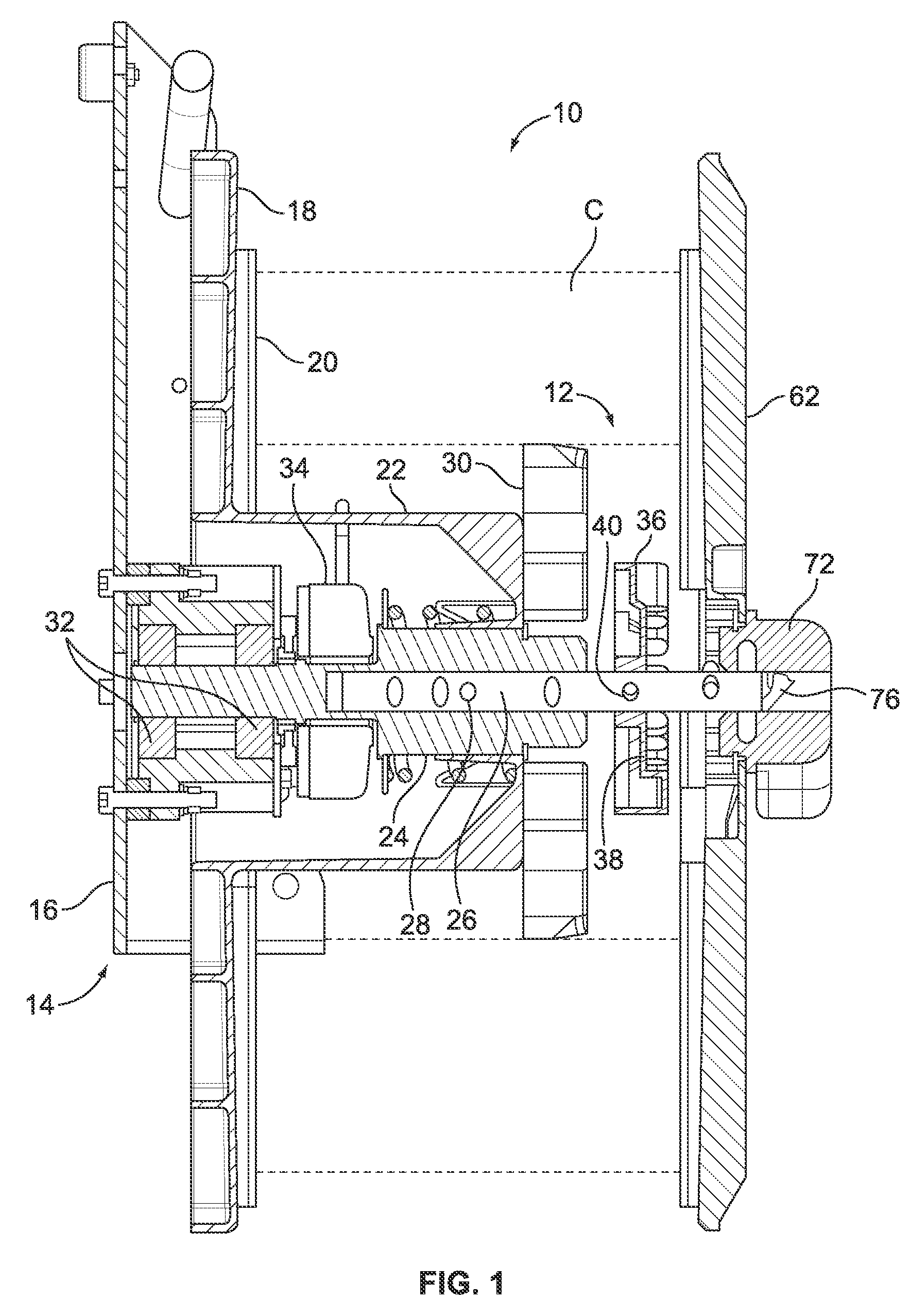
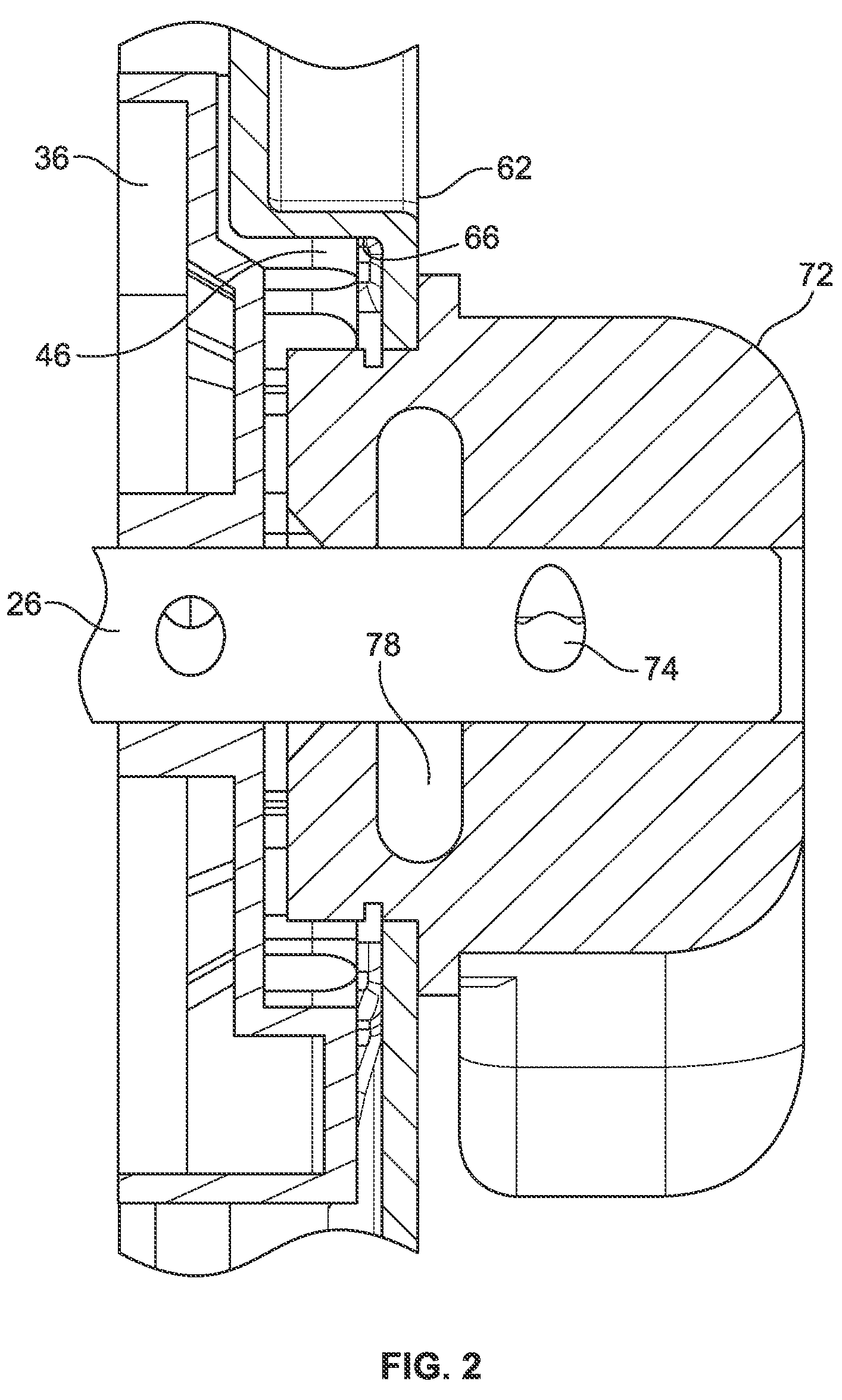
[0024]Referring now to the figures and in particular to FIG. 1, there is shown a cross-section of a portion of a strap dispenser 10 with an outer flange anti-rotation system 12 embodying the principles of the present invention. The dispenser 10 is mounted to a frame 14, which in the illustrated embodiment is a door 16, that is stationary...


PUM

PropertyMeasurementUnit
flexibleaaaaaaaaaa
rotationaaaaaaaaaa
anglesaaaaaaaaaa

Abstract

An anti-rotation system that prevents undesired rotation of an outer flange of a strap dispenser includes an anti-rotation element mounted to a shaft of the dispenser and the outer flange mounted to the anti-rotation element. The anti-rotation element and the outer flange have complementary mating surfaces such that when the shaft, on which the coil rotates, ceases rotation, the anti-rotation element, engaged with the outer flange, ceases rotation of the outer flange; thus, inertia of the coil cannot force the outer flange to rotate undesireably. A locking element abuts the outer flange to secure the flange to the anti-rotation element and a pin extends out from the shaft and inserts into a helical track in the locking element so that the pin rides in the helical track. The anti-rotation element also includes a through-bore for a fastener to secure the anti-rotation element to the shaft.

Description

CROSS-REFERENCE TO RELATED APPLICATION[0001]This application claims the benefit of priority of Provisional U.S. Patent Application Serial No. 61 / 185,085, filed Jun. 8, 2009, entitled “ANTI-ROTATION SYSTEM FOR STRAP DISPENSER OUTER FLANGE”.BACKGROUND OF THE INVENTION[0002]The present invention pertains to a strap dispenser. More particularly, the present invention pertains to an outer flange anti-rotation system for a strap dispenser for plastic or metal strap in coil form.[0003]Coil dispensers are used as a source or supply of coil material for many strapping operations. Coil dispensers can be free-standing, supported on carts or mounted to strapping machines. The coiled material is mounted on the dispenser so as to rotate to pay out strap.[0004]In many mounting configurations, dispensers have an outside flange, which is that flange that resides on the outside or accessible side of the dispenser. In some configurations, the outside flange remains inaccessible, but is that flange tha...

Claims


Application Information

Patent Timeline
Patent Type & Authority Patents(United States)
IPC IPC(8): B65H23/06
CPCB65B13/18B65B41/12B65H49/34B65H75/22B65H2701/375
Inventor BOBREN, ALLAN J.ELLIOTT, DUSTIN D.
Owner SIGNODE IND GRP
Why Eureka
Try Eureka