Rotor brake and windmilling lubrication system for geared turbofan engine

a geared turbofan and lubrication system technology, which is applied in the direction of engines, mechanical equipment, machines/engines, etc., can solve the problems of preventing affecting the operation of the turbofan engine, so as to prevent the rotation of the fan section

Active Publication Date: 2008-05-01
RTX CORP
View PDF14 Cites 29 Cited by
  • Summary
  • Abstract
  • Description
  • Claims
  • Application Information

AI Technical Summary

Benefits of technology

[0006]An example system provides an arrangement for preventing undesired rotation of the fan section of a turbofan engine and for supplying oil to the journal bearings during rotation of the fan section as a result of windmilling.

Problems solved by technology

In such an aircraft, one of the turbofan engines may shut-down during flight if a fault condition occurs.
Without some oil supply, the journal bearings may seize and harm the turbofan engine or prevent operation of the turbofan engine.
Preventing windmilling while the aircraft is in the air causes drag as the stationary fan section impedes airflow through the turbofan engine.
When the aircraft is on the ground, airflow through the turbofan engine may cause the fan section to windmill.
Without some oil supply while windmilling, the journal bearings may seize and harm the turbofan engine.

Method used


Image

  • Rotor brake and windmilling lubrication system for geared turbofan engine
  • Rotor brake and windmilling lubrication system for geared turbofan engine
  • Rotor brake and windmilling lubrication system for geared turbofan engine

Examples


Embodiment Construction

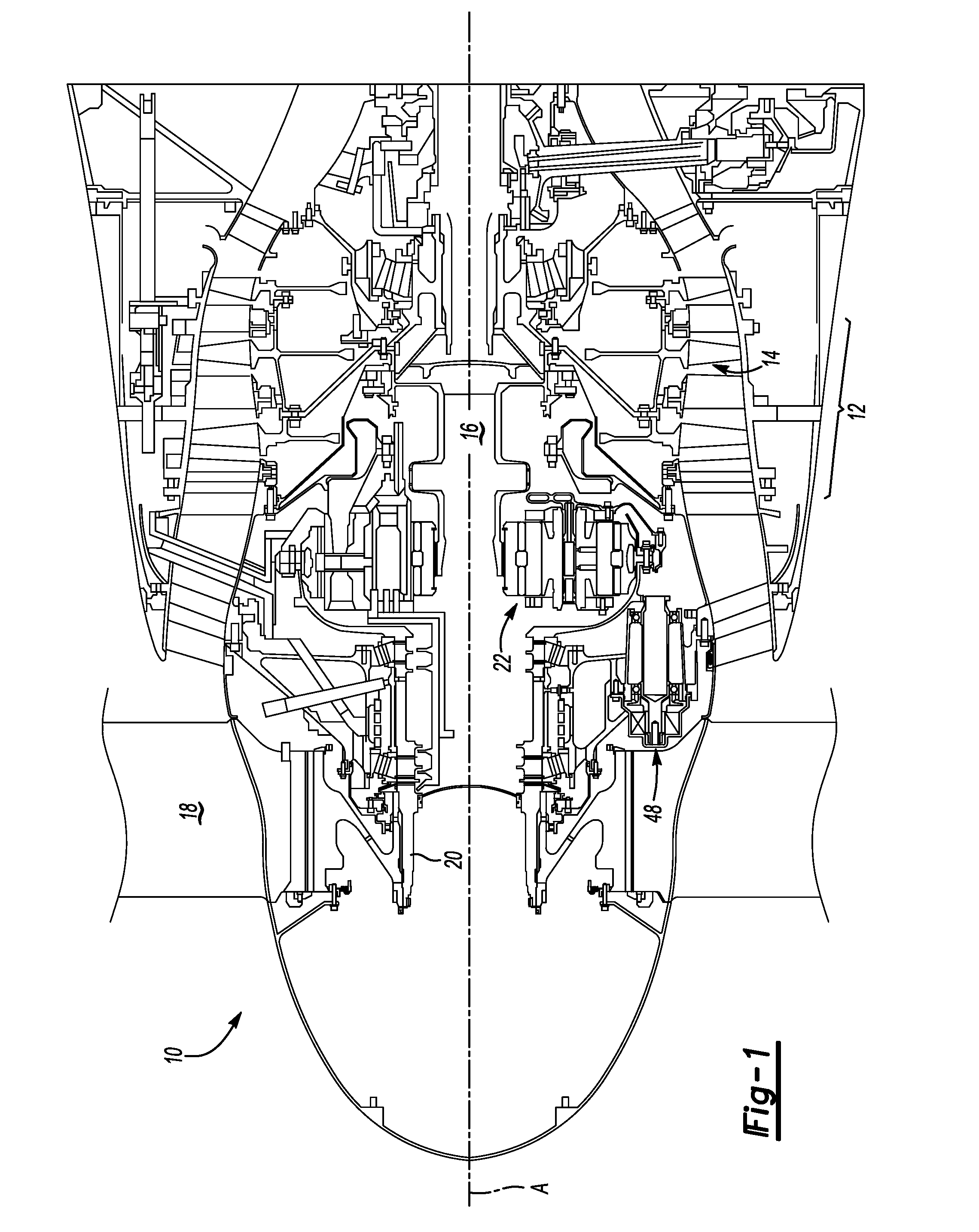
[0019]FIG. 1 is a schematic view of a portion of a turbofan engine 10. The turbofan engine 10 includes a compressor section 12 with compressor blades 14 that rotate about an axis A driven by a turbine shaft 16. A fan section 18 is supported on a fan shaft 20 and driven by the turbine shaft 16 using a planetary gear set 22.

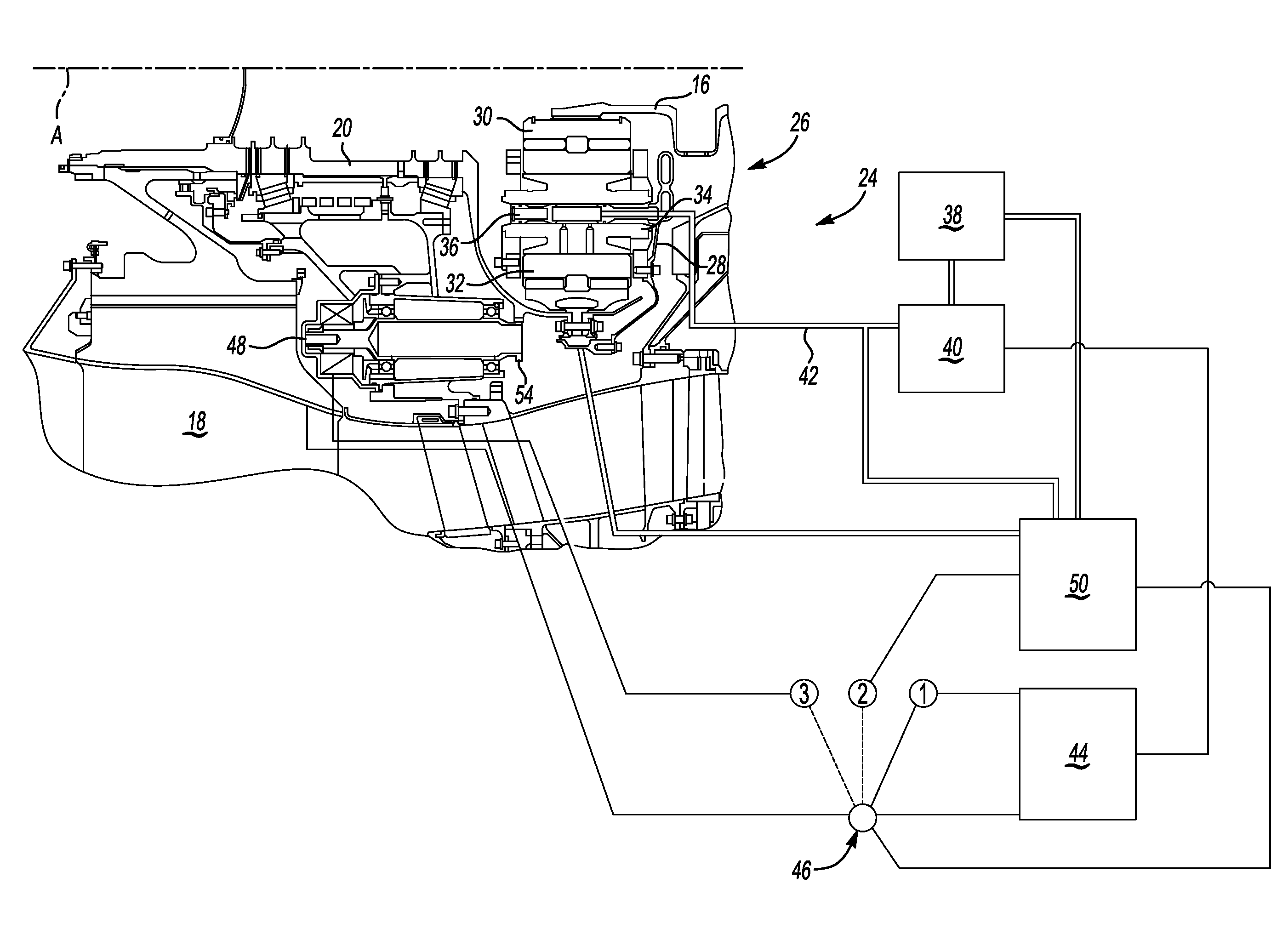
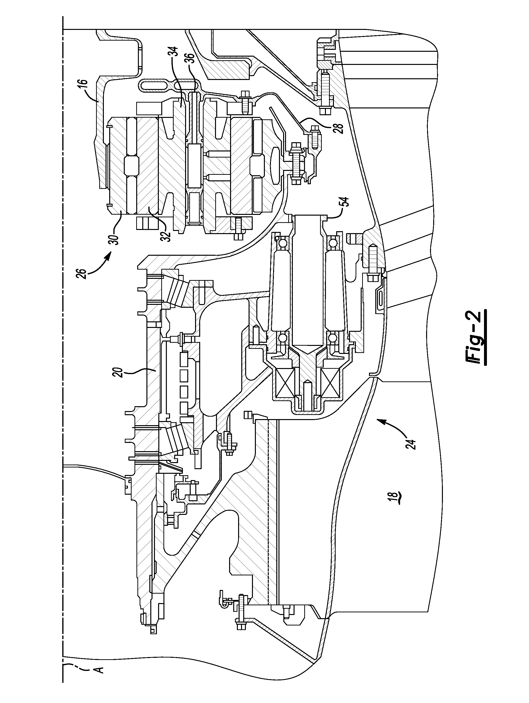
[0020]Referring now to FIG. 2, a fan drive gear system 26 rotates a fan shaft 20 to drive the fan section 18. The fan drive gear system 26 includes a sun gear 30 and a plurality of planetary gears 32 that engage the sun gear 30. Journal bearings 34 are located between the planetary gears 32 and support shafts 36 to reduce friction. The planetary gears 32 rotate relative to the journal bearings 34.

[0021]When the engine 10 is running, a primary oil pump 40 pumps oil from an oil supply 38 to lubricate the fan drive gear system 26 as shown in FIG. 3. The oil from the primary oil pump 40 communicates along an oil flow path 42 to the journal bearings 34.

[0022]An engine c...


PUM


Abstract

A journal bearing provides lubrication to planetary gears during windmilling operation of a fan section. A primary oil pump provides oil from an oil supply during driven operation of the fan and a secondary oil pump driven by a generator provides oil during windmilling operation of the fan. The generator acts as a dynamic brake when the aircraft is grounded to prevent windmilling. A switch selects between the primary and secondary oil pump and controls the brake application.

Description

BACKGROUND OF THE INVENTION[0001]This invention relates to an arrangement for protecting journal bearings of the fan drive systems for turbofan engines by preventing undesired rotation and supplying oil to the journal bearings during rotation.[0002]Turbofan engines include fan sections driven by planetary gear systems. Journal bearings in the systems reduce friction between planetary gears and corresponding support shafts. An oil system supplies oil to lubricate each of the journal bearings. An oil pump maintains pressure within the oil system to ensure each of the journal bearings receives an adequate supply of oil.[0003]Turbofan engines may be used to propel a multi-engine aircraft. In such an aircraft, one of the turbofan engines may shut-down during flight if a fault condition occurs. The oil pump also shuts down when the turbofan engine is not operating. Although the turbofan engine is shut down, airflow through the moving engine may continue to rotate (i.e., windmill) the fan ...

Claims


Application Information

Patent Timeline
Patent Type & Authority Applications(United States)
IPC IPC(8): F02K3/02
CPCF01D15/10F01D15/12F01D21/006F05D2220/76F02C7/32F05D2260/40311F05D2270/09F01D25/20
Inventor SHERIDAN, WILLIAM G.
Owner RTX CORP
Why Eureka
Try Eureka