Stand up seat assembly with retractable rear leg

a technology of seat assembly and rear leg, which is applied in the direction of movable seats, dismountable/non-movable seats, roofs, etc., can solve the problems of difficult and cumbersome movement of the second row seating in this manner, and the area of ingress and egress is often uncomfortably small

Active Publication Date: 2012-12-25
INTIER AUTOMOTIVE INC
View PDF9 Cites 6 Cited by
  • Summary
  • Abstract
  • Description
  • Claims
  • Application Information

AI Technical Summary

Problems solved by technology

Thus, passengers do not have direct access to the third row seating.
Movement of the second row seating in this manner can be difficult and cumbersome, and the area of ingress and egress is often uncomfortably small.

Method used


Image

  • Stand up seat assembly with retractable rear leg
  • Stand up seat assembly with retractable rear leg
  • Stand up seat assembly with retractable rear leg

Examples


Embodiment Construction

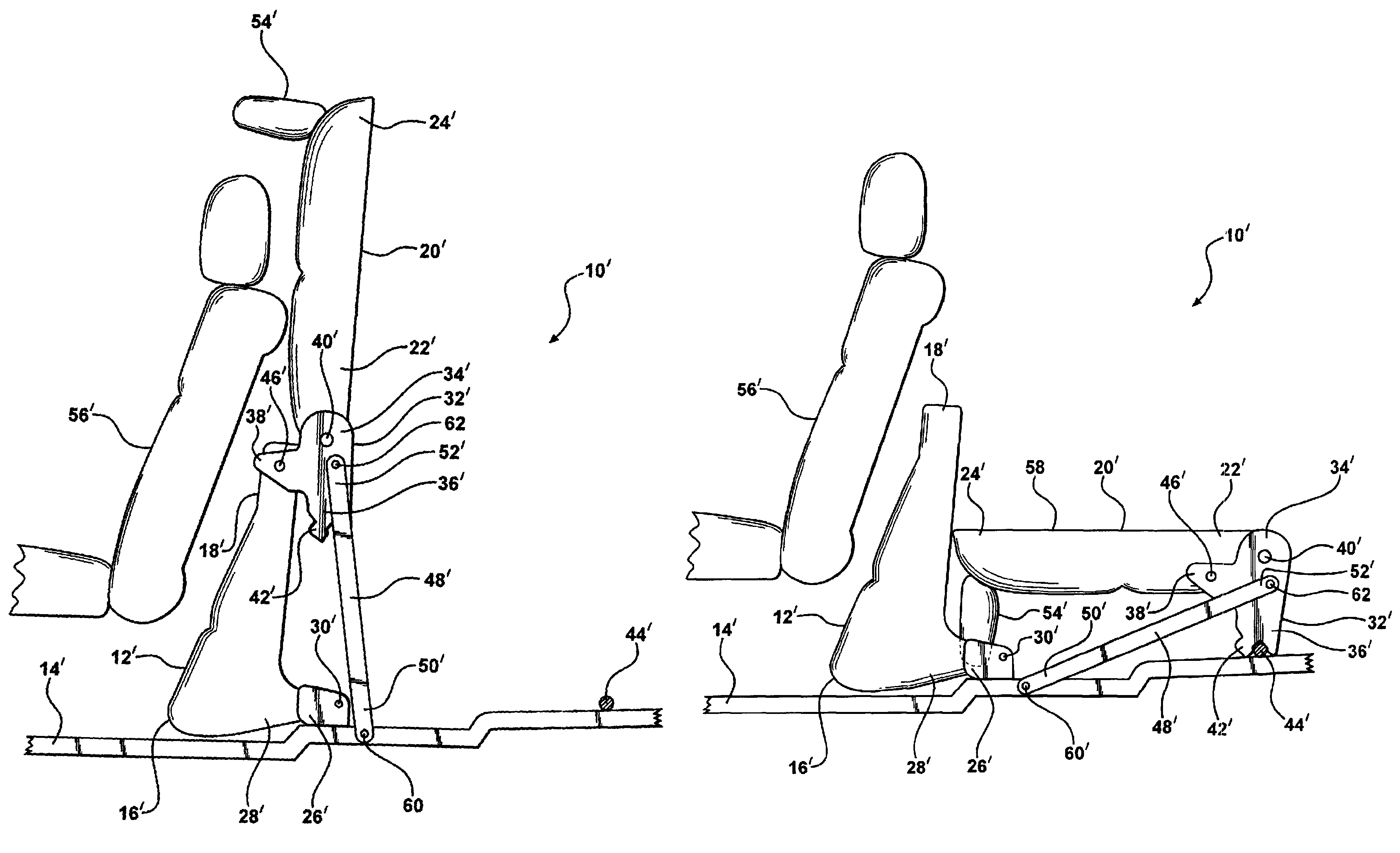
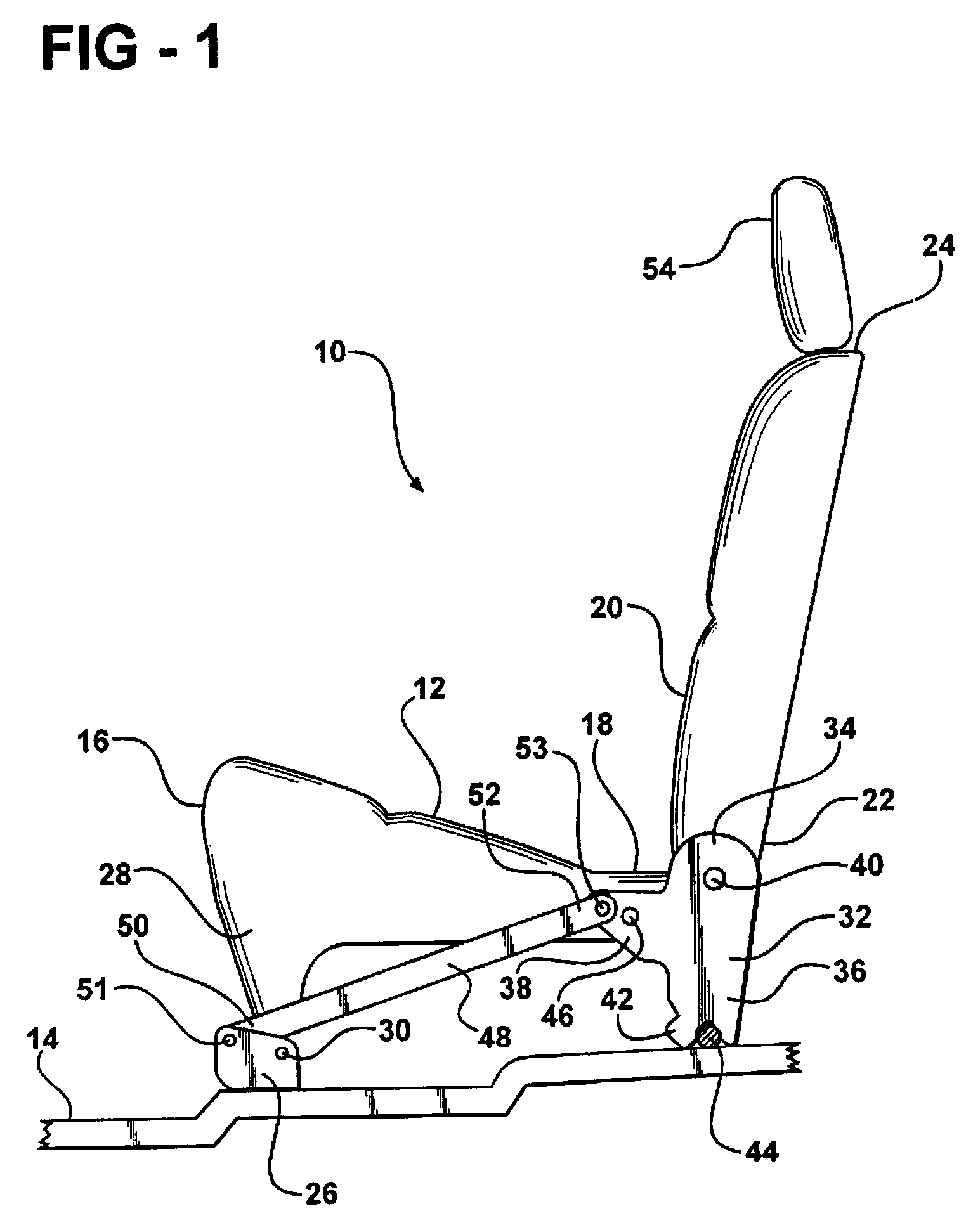
[0017]Referring to FIG. 1, a seat assembly for an automotive vehicle is generally shown at 10. The seat assembly 10 includes a seat cushion 12 for supporting a seat occupant above a floor 14 of the vehicle. The seat cushion 12 extends between a front end 16 and an opposite rear end 18. The seat assembly 10 also includes a seat back 20 for supporting a back of the seat occupant. The seat back 20 extends between a lower end 22 and an opposite upper end 24. The lower end 22 of the seat back 20 is operatively coupled to the rear end 18 of the seat cushion 12.

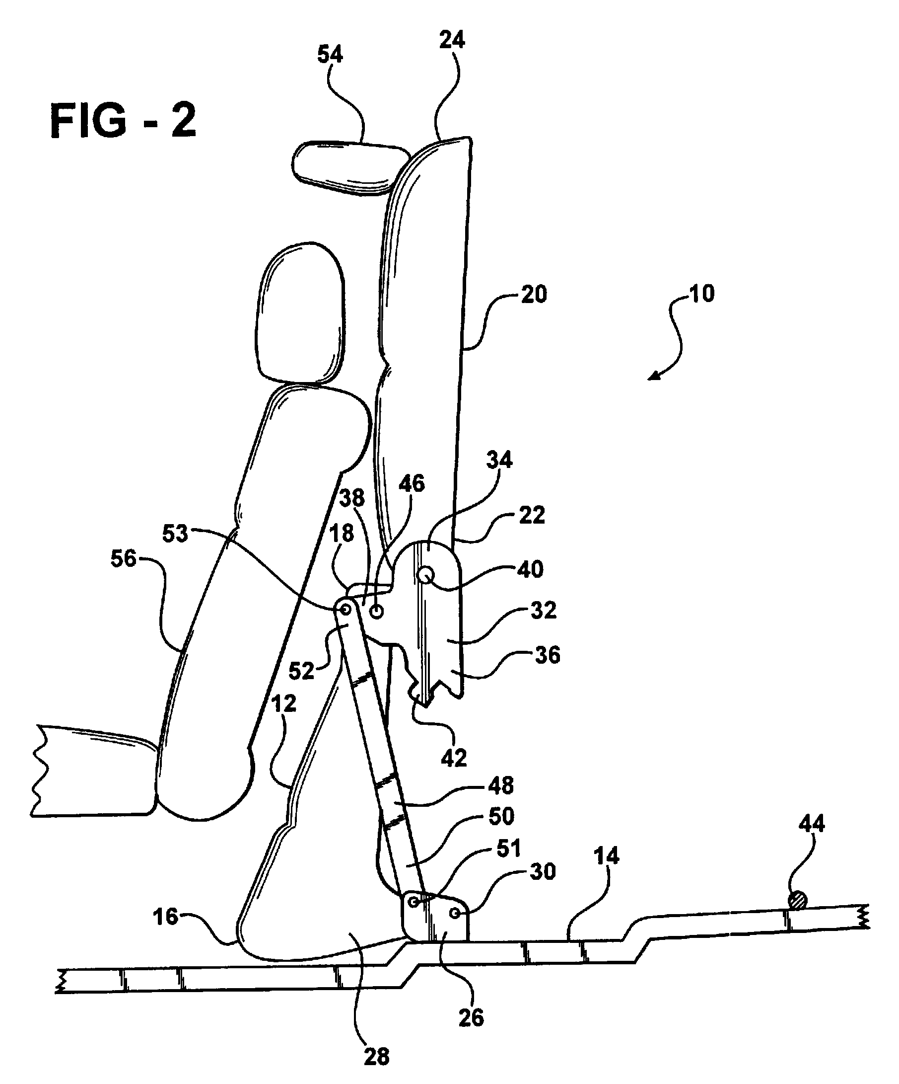
[0018]A forward floor bracket 26 is mounted to the floor 14 of the vehicle. The front end 16 of the seat cushion 12 includes a downward extending portion or a front leg 28 that is pivotally coupled to the floor bracket 26 at a first main pivot 30. The seat cushion 12 pivots about the first main pivot 30 between a generally horizontal seating position, shown in FIG. 1, and a generally vertical kneeling position, shown in FIG. 2. In t...


PUM


Abstract

A seat assembly is provided for supporting an occupant above a floor in a vehicle. The seat assembly includes a seat cushion extending between front and rear ends. The front end is adapted to be pivotally coupled to the floor for pivoting the seat cushion between a seating position and a kneeling position. A seat back is pivotally coupled to the rear end of the seat cushion and is adapted to be releasably secured to the floor. A drive link is pivotally coupled between the floor and the seat back. The drive link urges the seat back to pivot relative to the seat cushion as the seat cushion pivots between the seating and kneeling positions thereby maintaining the seat back in a generally vertical orientation.

Description

CROSS REFERENCE TO RELATED APPLICATION[0001]This application claims priority to and all the benefits of U.S. Provisional Application Ser. No. 60 / 872,693, filed on Dec. 4, 2006 and entitled “Stand Up Seat with Retractable Rear Leg.”BACKGROUND OF THE INVENTION[0002]1. Field of the Invention[0003]The invention relates to a seat assembly for an automotive vehicle. More particularly, the invention relates to a seat assembly that is capable of being moved forward and upward to a stand-up position to provide access to a rearward area of an automotive vehicle.[0004]2. Description of Related Art[0005]It is common in certain mini-van and sport utility vehicles to provide second and third row seating. Typically, the vehicle includes a pair of front doors adjacent front row seating and a pair of rear doors located adjacent the second row seating. The third row seating is located at the generally furthermost rear portion of the vehicle and is not located adjacent a door opening. Thus, passengers...

Claims


Application Information

Patent Timeline
Patent Type & Authority Patents(United States)
IPC IPC(8): B60N2/30
CPCB60N2/0292B60N2/3011B60N2/3031B60N2/4858B60N2/3065B60N2/309B60N2/36B60N2/305B60N2/859B60N2/30B60N2/02B60N2/20
Inventor ZEIMIS, III, PETER PAULSZYBISTY, ROBERT J.CARROLL, JEFFREY P.MCLAUGHLIN, MATTHEW J.HURST, III, NELSON E.
Owner INTIER AUTOMOTIVE INC
Why Eureka
Try Eureka