Sludge extraction system for biological waste water reactors

a biological waste water and extraction system technology, applied in the direction of water/sewage multi-stage treatment, other chemical processes, separation processes, etc., can solve the problems of complicated and therefore expensive manufacturing of a reactor of this type, and achieve the effects of cost effective production, cost effective and cost effectiv

Active Publication Date: 2013-01-15
VOITH PATENT GMBH +1
View PDF12 Cites 1 Cited by
  • Summary
  • Abstract
  • Description
  • Claims
  • Application Information

AI Technical Summary

Benefits of technology

[0011]Due to the fact that at least one diverting means is provided in the lower region of the reactor vessel which includes at least one diagonally extending section and which is designed and / or arranged so that solids sinking to the bottom from the upper reactor region are deflected such that in the reactor the solids settle in the region of the solid matter discharge pipe and can thus be discharged from the reactor through the at least one solid matter discharge pipe, the solids sinking downward during reactor operation do not settle uniformly in large areas on the reactor bottom, but are directed in a targeted manner to that location on the reactor bottom where the solid matter discharge pipe(s) is / are located. This achieves a constructively simple and cost effective measure in that solids sinking downward during reactor operation can be completely or at least almost completely removed from the reactor, thereby rendering periodic shut-down of the reactor for the purpose of removing accumulated sediment unnecessary. For these reasons a conically downward tapering reactor section can be foregone in the inventive reactor. Instead, a constructively simpler and more cost effective flat bottom or round bottom is provided in the inventive reactor.
[0014]According to a first embodiment of the current invention, the diverting means is in the embodiment of a deflector plate which, relative to the horizontal, has a slant (α) between approximately 10° and 80°, for example between approximately 20° and 70°, approximately between 30° and 60° or between approximately 35° and 50°. A reliable, and in particular a complete diversion of the solids sinking down in the reactor can hereby be achieved, thus ensuring that no solid matter remains adhered on the diverting means.
[0016]In order to avoid a mechanical overload of the at least one deflector plate during operation of the reactor due to the weight of the waste water in the reactor and to thereby enable a constructively simple and cost effective embodiment of the at least one deflecting plate, the at least one deflector plate may be arranged so that the waste water in the reactor can flood it from the rear. In this way the at least one deflector plate is subjected to only minimal loads during the operation of the reactor.
[0021]According to this embodiment of the present invention, the deflector plates can also be flooded from the rear which can be achieved, for example, in that the four deflector plates terminate at a distance from the reactor outside wall. The four deflector plates occupy, for example, a total of approximately 10 to 95%, approximately 30 to 90% or approximately 70 to 90% of the reactor cross section in order to reliably ensure a diversion of the sinking solids across the entire cross section of the reactor toward to the reactor center.
[0023]According to a second embodiment of the current invention a diverting means is provided in the lower region of the reactor vessel which, viewed from the reactor bottom, has the form of an inverted truncated hollow cone, which is, for example, arranged centered in the reactor. In this way too, reliable diversion of the downward sinking solids in the reactor into the region of the solid matter discharge pipe mouth is achieved through a constructively simple, cost effectively producible diverting means. This embodiment of the present invention is suitable for reactors having, for example, a round or oval cross section. According to this embodiment of the present invention, the diverting means can also be flooded from the rear which is why the outside edge of the truncated hollow cone may be located at a distance from the outside reactor wall. The truncated hollow cone can occupy, for example, approximately 10 to 95%, approximately 30 to 90% or approximately 70 to 90% of the reactor cross section. According to this embodiment of the present invention, the at least one solid matter discharge pipe leads, for example, into the region of the opening provided on the top surface of the truncated hollow cone which can be any desired cross sectional shape, for example round, oval, rectangular or square.
[0024]According to a third embodiment of the current invention the at least one diverting means is bulk material arranged on the reactor bottom and is, for example, arranged in the form of a negative cone. The supply pipes should hereby terminate above the bulk material cone. In addition to the fact that in this way too a reliable diversion of the downward sinking solids in the reactor into the region of the solid matter discharge pipe mouth is achieved through a constructively simple, cost effectively producible diverting means this embodiment of the present invention offers the advantage that the diverting means are particularly cost effective. According to this embodiment of the present invention, the at least one solid matter discharge pipe is provided, for example, in the region of the tip of the negative cone of bulk material. A separating wall extending vertically in an upward direction can be provided on the reactor bottom in the region of the center of the reactor and, between the two side surfaces of the separation wall and the reactor outside wall, bulk material may respectively be provided as a diverting means, each in the form of a negative cone. In this embodiment, two solid matter discharge pipes may be provided in the reactor, whereby each respectively leads into the region of the tip of one of the two negative cones of bulk material.

Problems solved by technology

Moreover, manufacture of a reactor of this type is very complicated and therefore expensive.

Method used


Image

  • Sludge extraction system for biological waste water reactors
  • Sludge extraction system for biological waste water reactors
  • Sludge extraction system for biological waste water reactors

Examples


second embodiment

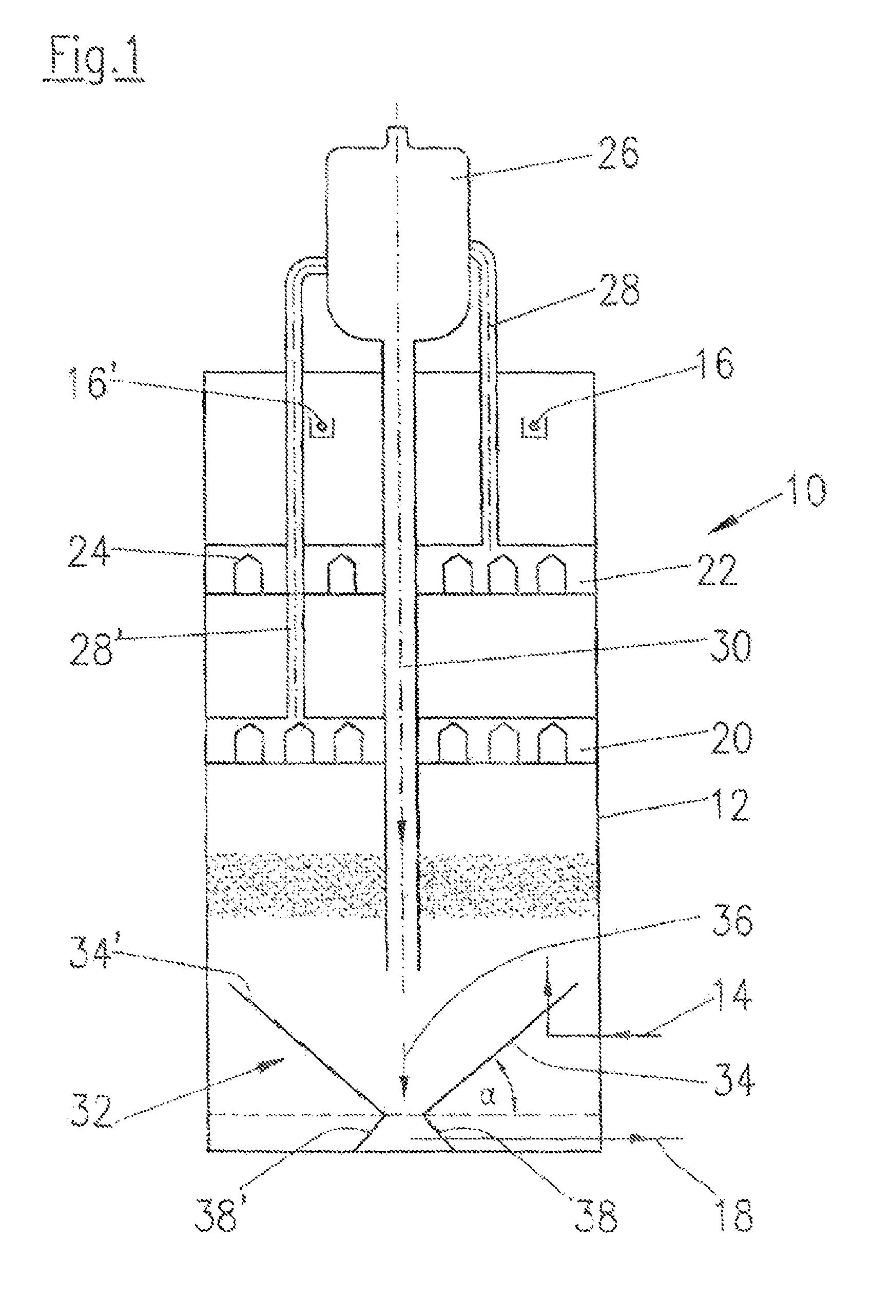
[0040]Referring now to FIG. 2 there is shown a schematic longitudinal view of the lower region of reactor 10 for anaerobic purification of waste water in accordance with the current invention. In this embodiment, diverting means 32 is provided by bulk material 40 which is arranged in the shape of a negative cone. The surface of negative bulk material cone 40 is indicated in FIG. 2 by reference number 42. During operation of the reactor in accordance with this embodiment of the present invention, the solids descending in reactor 10 are diverted on surface 42 of the negative bulk material cone 40 toward the tip of the negative cone located at the center of the reactor where solid matter discharge pipe 18 is located through which the sediment is completely removed from reactor 10.

third embodiment

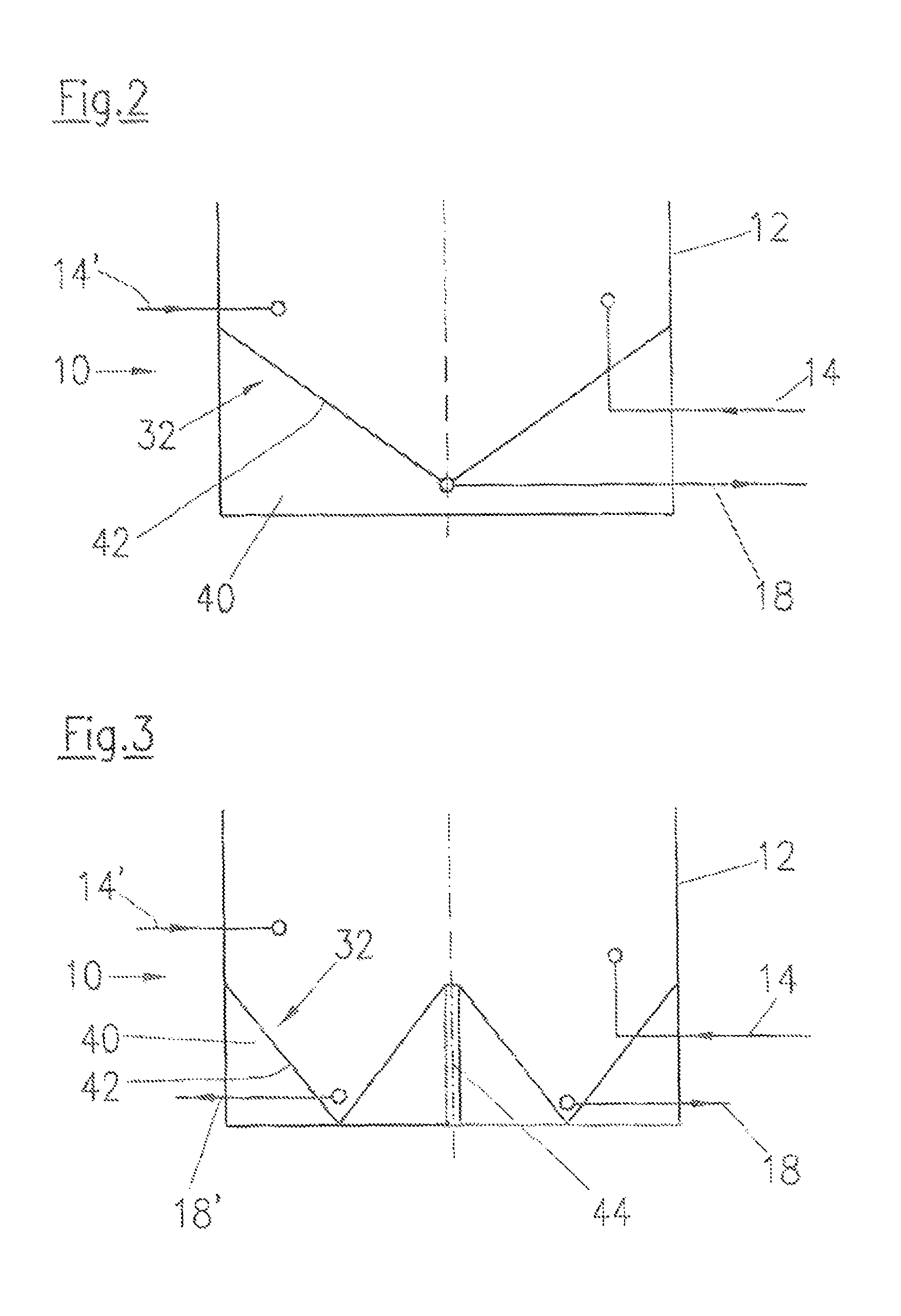
[0041]Referring now to FIG. 3, there is shown a schematic longitudinal view of the lower region of reactor 10 for anaerobic purification of waste water in accordance with the current invention. In this embodiment, diverting means 32 is also provided by bulk material 40. In contrast to the embodiment illustrated in FIG. 2, separating wall 44 extending vertically in an upward direction is provided, in this instance, on the reactor bottom in the region of the center of the reactor, whereby between the two side surfaces of separation wall 44 and the reactor outside wall bulk material 40 is arranged respectively in the form of a negative cone as diverting means 32. In the respective regions of the tips of the two negative cones, solid matter discharge pipes 18, 18′ are provided through which the solid matter is removed from reactor 10.

[0042]While this invention has been described with respect to at least one embodiment, the present invention can be further modified within the spirit and ...


PUM

PropertyMeasurementUnit
distanceaaaaaaaaaa
specific weightaaaaaaaaaa
areasaaaaaaaaaa

Abstract

A reactor for biological purification of waste water includes a reactor vessel having a substantially flat or a round bottom, at least one supply pipe arranged in a lower region of the reactor vessel for feeding the waste water to be purified into the reactor, at least one fluid discharge pipe for discharging purified waste water from the reactor, at least one solid matter discharge pipe arranged in the lower region of the reactor vessel for discharging solid matter from the reactor and at least one diverting means including at least one diagonally extending section. The at least one diverting means is designed and / or arranged so that solids sinking to the bottom of the reactor from the upper region of the reactor are deflected so that the solids settle in a region of the at least one solid matter discharge pipe and are discharged from the reactor through the at least one solid matter discharge pipe.

Description

CROSS REFERENCE TO RELATED APPLICATIONS[0001]This is a continuation of PCT application No. PCT / EP2010 / 050611, entitled “SLUDGE EXTRACTION SYSTEM FOR BIOLOGICAL WASTEWATER REACTORS”, filed Jan. 20, 2010, which is incorporated herein by reference.BACKGROUND OF THE INVENTION[0002]1. Field of the Invention[0003]The current invention relates to a reactor for biological, in particular anaerobic, purification of waste water including a reactor vessel having a substantially flat or round bottom, at least one supply line arranged in the lower region of the reactor vessel for feeding waste water to be purified into the reactor, at least one fluid discharge pipe for discharging purified waste water from the reactor, and at least one discharge pipe for solid matter arranged in the lower region of the reactor vessel for discharging solid matter from the reactor.[0004]2. Description of the Related Art[0005]A multitude of mechanical, chemical and biological methods and corresponding reactors are k...

Claims


Application Information

Patent Timeline
Patent Type & Authority Patents(United States)
IPC IPC(8): C02F3/28C02F11/04
CPCC02F3/2846B01J2219/00774B01J2219/1946C02F11/04C02F2203/006
Inventor GOMMEL, AXELEFINGER, DIETERGESSLER, WERNERMULDER, RONALD
Owner VOITH PATENT GMBH
Why Eureka
Try Eureka