Aircraft engine assembly comprising a fan cowl-supporting cradle mounted on two separate elements

a technology of engine assembly and fan, which is applied in the direction of machine supports, transportation and packaging, and other domestic objects, can solve the problems of substantial modification of the global geometry of the assembly, and more specifically of the nacelle, and is detrimental to the overall performance level of the aircraft, so as to reduce the harmful effects of misalignment, reduce the damage of the engine, and improve the accompanying deformation

Active Publication Date: 2013-01-22
AIRBUS OPERATIONS (SAS)
View PDF18 Cites 1 Cited by
  • Summary
  • Abstract
  • Description
  • Claims
  • Application Information

AI Technical Summary

Benefits of technology

[0015]Therefore, with the proposed arrangement it is possible largely to limit the harmful effects of misalignment described above, since the forward part of the cradle of the forward aerodynamic structure carrying the fan cowls is henceforth capable of better accompanying deformation of the engine when strong demand is placed on the assembly. Therefore the flush junction between the nacelle air intake and the fan cowls can be maintained, which allows limitation of drag losses encountered with prior art embodiments. In this respect, the drag losses are also reduced by maintaining the flush junction between the aerodynamic cowling and the other aerodynamic fairing of the mounting pylon, through the presence of the aft mounting means, and these drag losses are similarly reduced by maintaining the flush junction between the aerodynamic fairing and the air intake, through the presence of the forward mounting means.
[0016]Additionally, with this particular arrangement it is advantageously possible to limit the forward cantilever previously encountered with the structural cradle carrying the fan cowls, since this cradle is now equipped with forward mounting means mounted on the fan case of the engine.
[0020]Therefore the combination of the forward attachment and of the two aft semi-attachments, forming the mounting means for the forward aerodynamic structure, allows mounting means to be obtained which are advantageously strongly close to an isostatic mounting system.

Problems solved by technology

However, if the engine assembly is subjected to major stresses such as those encountered during take-off and landing phases, or when flying in strong turbulence, the securing of the cradle of the forward aerodynamic structure to the rigid structure leads to a substantial modification of the global geometry of the assembly, and more specifically of the nacelle.
In particular, misalignment accompanying engine deformation may be observed between the air intake of the nacelle and the fan cowls mounted on said forward aerodynamic structure secured to the rigid structure of the mounting pylon, this forward aerodynamic structure therefore possibly also being drawn away from the same nacelle air intake.
The phenomenon observed evidently causes drag, which is detrimental to the overall performance level of the aircraft.

Method used


Image

  • Aircraft engine assembly comprising a fan cowl-supporting cradle mounted on two separate elements
  • Aircraft engine assembly comprising a fan cowl-supporting cradle mounted on two separate elements
  • Aircraft engine assembly comprising a fan cowl-supporting cradle mounted on two separate elements

Examples


Embodiment Construction

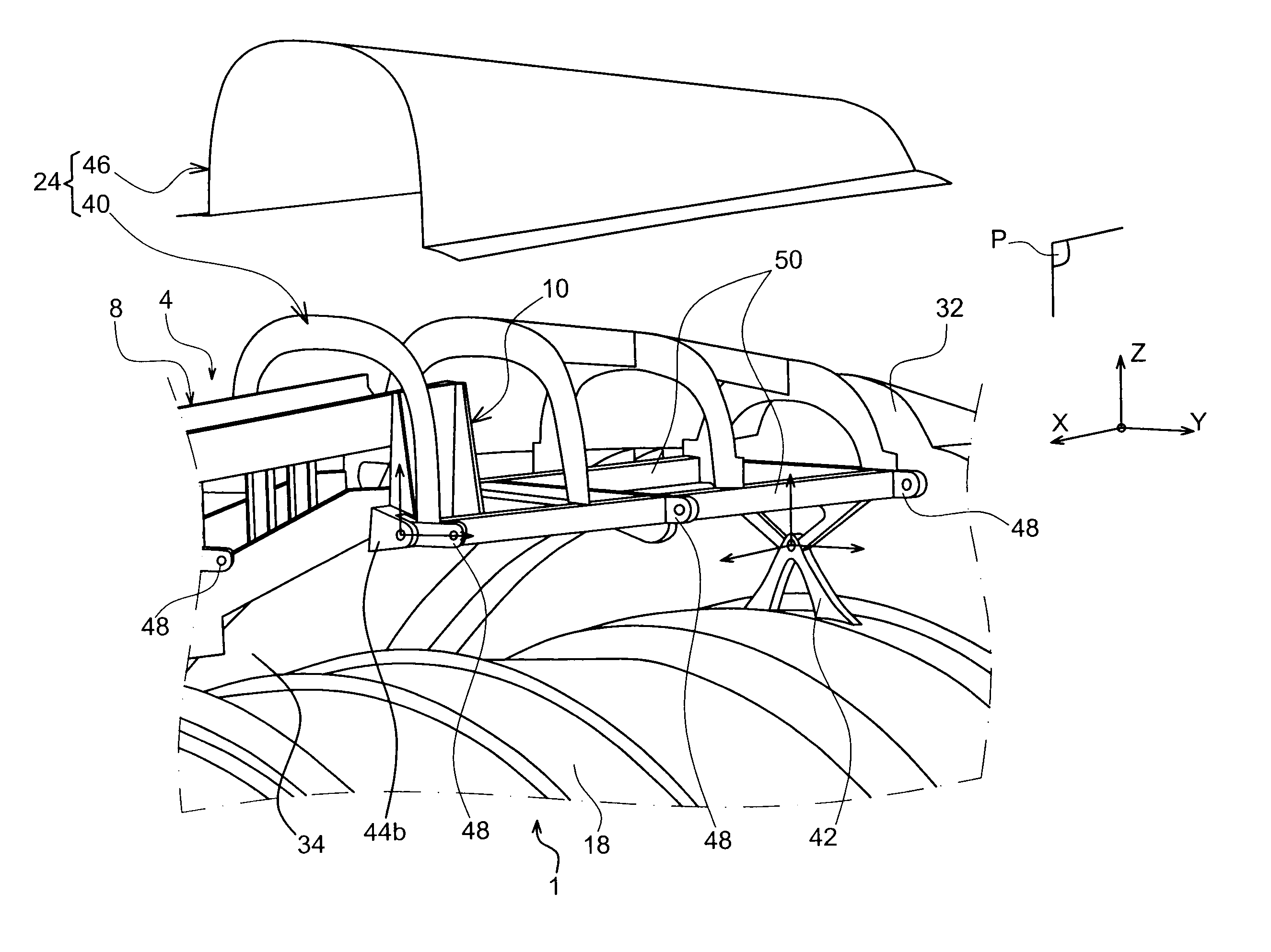
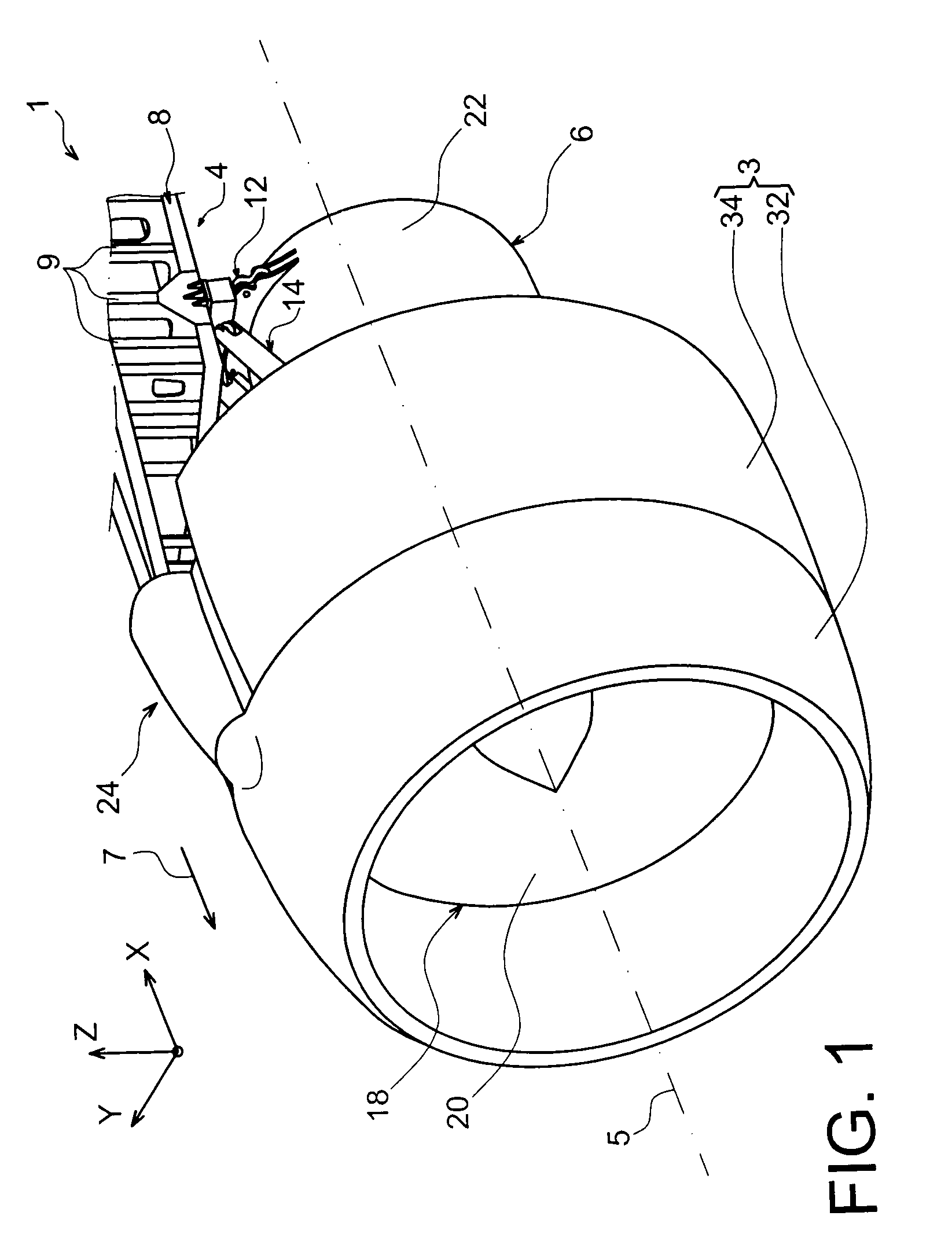
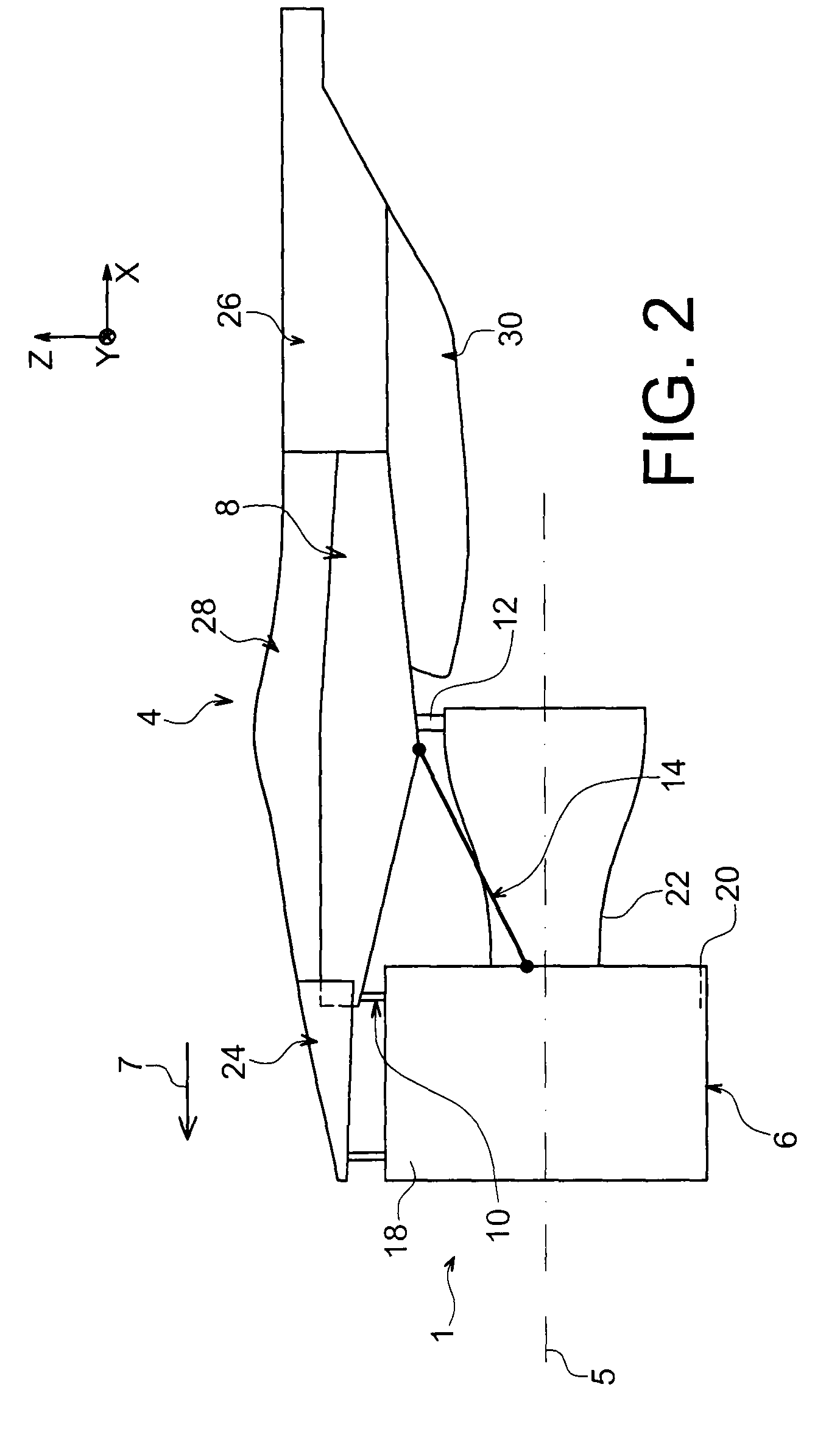
[0032]With reference firstly to FIGS. 1 and 2, an aircraft engine assembly 1 can be seen intended to be attached below a wing of this aircraft (not shown), this assembly 1 comprising a mounting structure 4, an engine 6 such as a turbojet engine mounted below this structure 4, and a nacelle 3 of which only the forward portion is shown FIG. 1.

[0033]In the remainder of this description X is used to designate the longitudinal direction of the structure 4 which is comparable to the longitudinal direction of the turbojet engine 6, this direction X lying parallel to a longitudinal axis 5 of this turbojet engine 6. Y is used to designate the direction oriented substantially transversally relative to the structure 4 and also comparable to the transverse direction of the turbojet engine 6, and Z designates the vertical direction or height, these three directions X, Y and Z lying orthogonal to one another.

[0034]Also, the terms > and > are to be considered relative to the direction of travel of...


PUM


Abstract

An aircraft engine assembly including an engine, an engine mounting structure, and a nacelle surrounding the engine and including fan cowls. The mounting structure includes a rigid structure and a forward aerodynamic structure on which the fan cowls are hinged, the forward aerodynamic structure including a cradle provided with an aft mounting mechanism mounted on the rigid structure. The cradle also includes a forward mounting mechanism mounted on a fan case of the engine.

Description

TECHNICAL AREA[0001]The present invention generally relates to an aircraft engine assembly comprising an engine, an engine mount and a nacelle surrounding the engine and provided with fan cowls, the above-mentioned mount comprising a rigid structure and a forward aerodynamic structure on which the fan cowls are movably mounted.[0002]This type of device also called a mounting pylon or <<EMS >> for Engine Mounting Structure globally allows an engine such as a gas turbine engine to be mounted below the wing of an aircraft, or allows the mounting of this engine above the wing or even onto an aft portion of the fuselage of the aircraft.STATE OF THE PRIOR ART[0003]Said mounting structure is effectively provided so as to form a connecting interface between an engine and an aircraft wing. It enables the loads generated by the associated engine to be transmitted to the frame of this aircraft, and also provides a pathway for fuel, electric, hydraulic and air supply lines between t...

Claims


Application Information

Patent Timeline
Patent Type & Authority Patents(United States)
IPC IPC(8): B64D27/00
CPCB64D27/18B64D2027/264
Inventor ROCHE, FREDERICMARTINOU, JEAN-MARC
Owner AIRBUS OPERATIONS (SAS)
Why Eureka
Try Eureka