Aircraft engine assembly comprising a junction aerodynamic fairing mounted on two separate elements

a technology of aerodynamic fairing and assembly, which is applied in the direction of machines/engines, liquid fuel engines, power plant inspection panels, etc., can solve the problems of significant modification of the overall geometry of the assembly, and more specifically the geometry of the nacelle, and may be observed misalignment accompanying engine deformation, so as to reduce the harmful effects of misalignment, reduce the effect of drag loss, and improve the response to engine deformation

Active Publication Date: 2012-04-24
AIRBUS OPERATIONS (SAS)
View PDF12 Cites 45 Cited by
  • Summary
  • Abstract
  • Description
  • Claims
  • Application Information

AI Technical Summary

Benefits of technology

[0015]Therefore, with the proposed arrangement it is possible largely to limit the harmful effects of misalignment described above, since the particular securing of the junction aerodynamic fairing henceforth permits better response to engine deformation when strong demand is placed on the assembly. This advantageously allows drag losses to be limited which are encountered in prior art embodiments.

Problems solved by technology

However, when the engine assembly is subjected to heavy stresses such as those encountered during take-off or landing phases or when flying in strong turbulence, and more simply under the effect of engine torque, engine thrust and thermal expansion, the securing of the cradle of the forward aerodynamic structure to the engine structure leads to a substantial modification in the overall geometry of the assembly, and more specifically the geometry of the nacelle.
In particular, misalignment accompanying engine deformation may be observed between the air intake of the nacelle and the cradle aerodynamic cowling fixedly carried by the cradle which is joined to the rigid structure of the mounting pylon.
The phenomenon observed evidently causes drag, which is detrimental to the overall performance of the aircraft.

Method used


Image

  • Aircraft engine assembly comprising a junction aerodynamic fairing mounted on two separate elements
  • Aircraft engine assembly comprising a junction aerodynamic fairing mounted on two separate elements
  • Aircraft engine assembly comprising a junction aerodynamic fairing mounted on two separate elements

Examples


Embodiment Construction

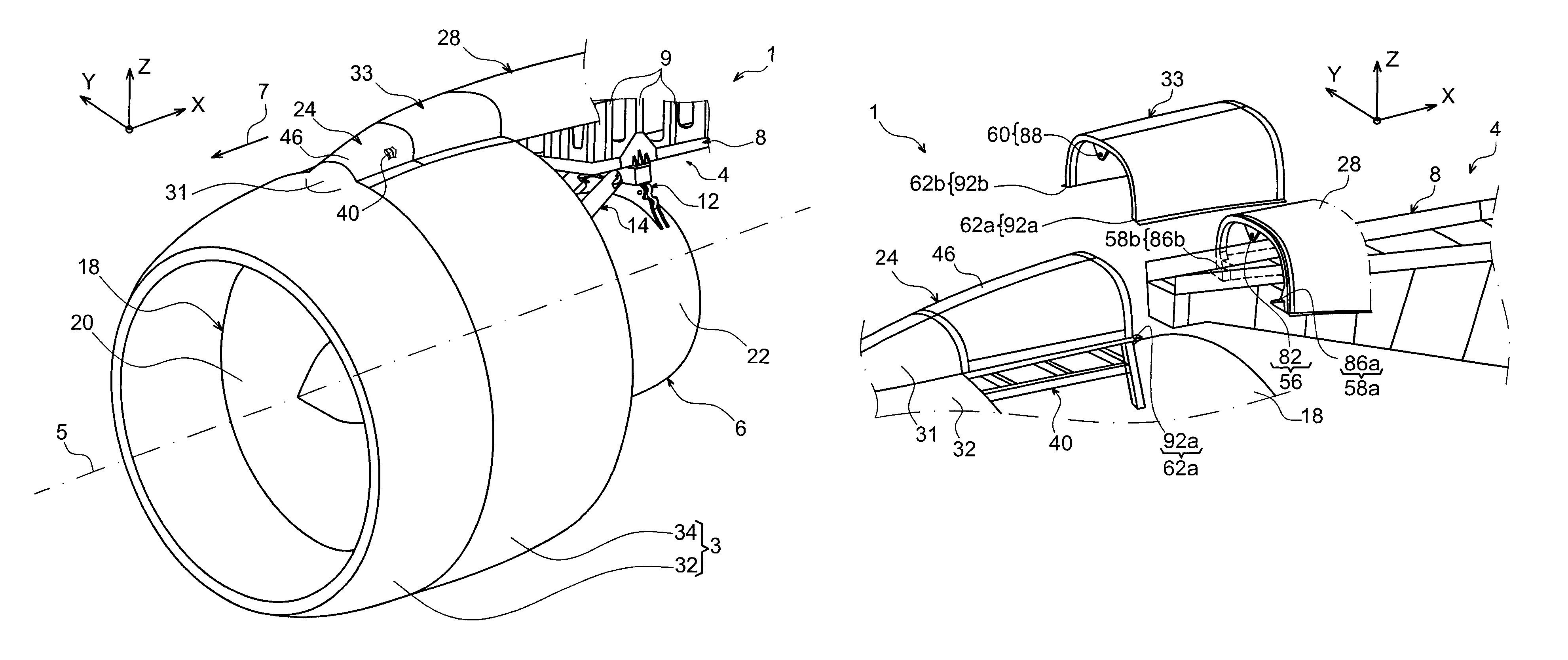
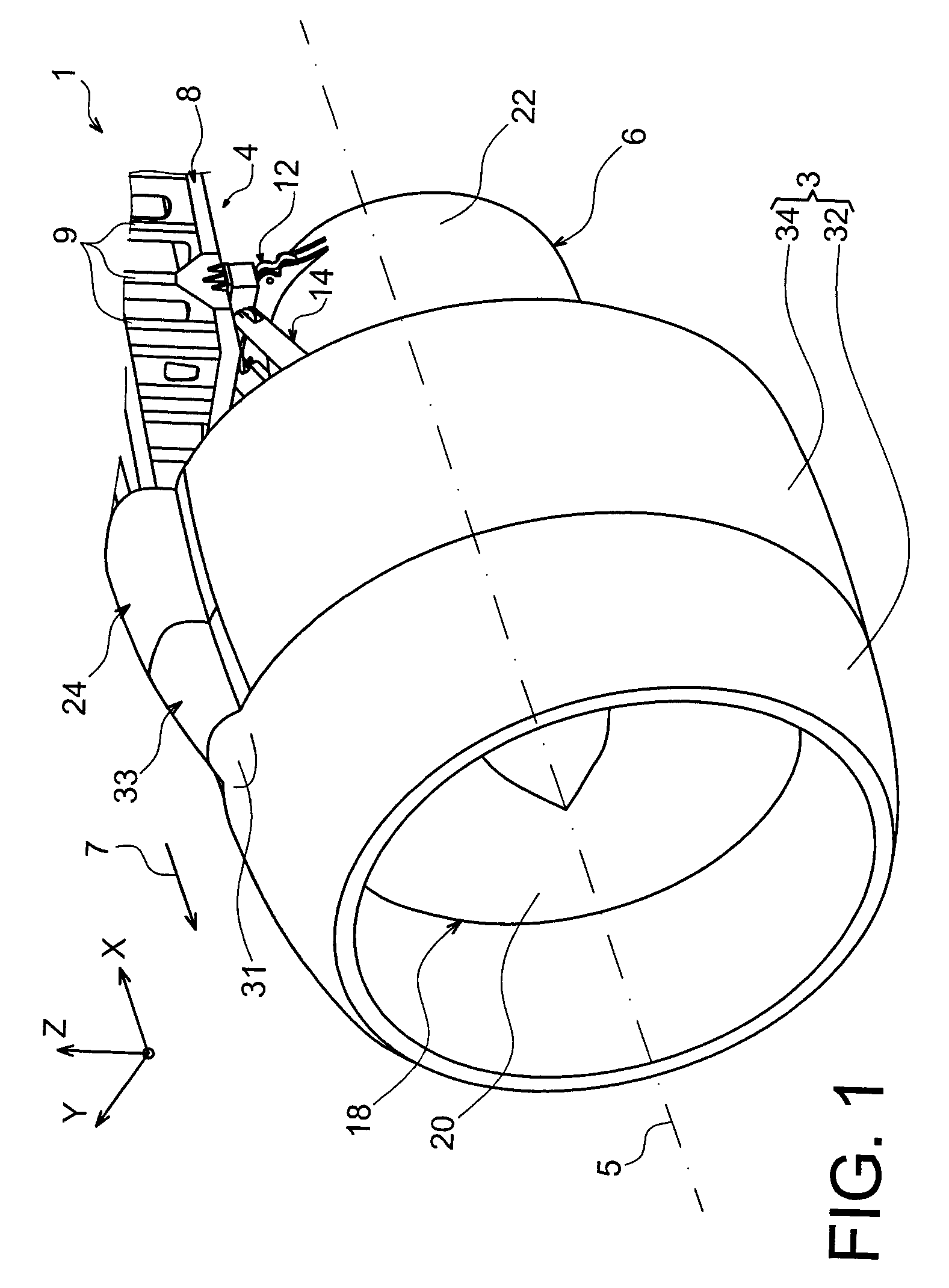
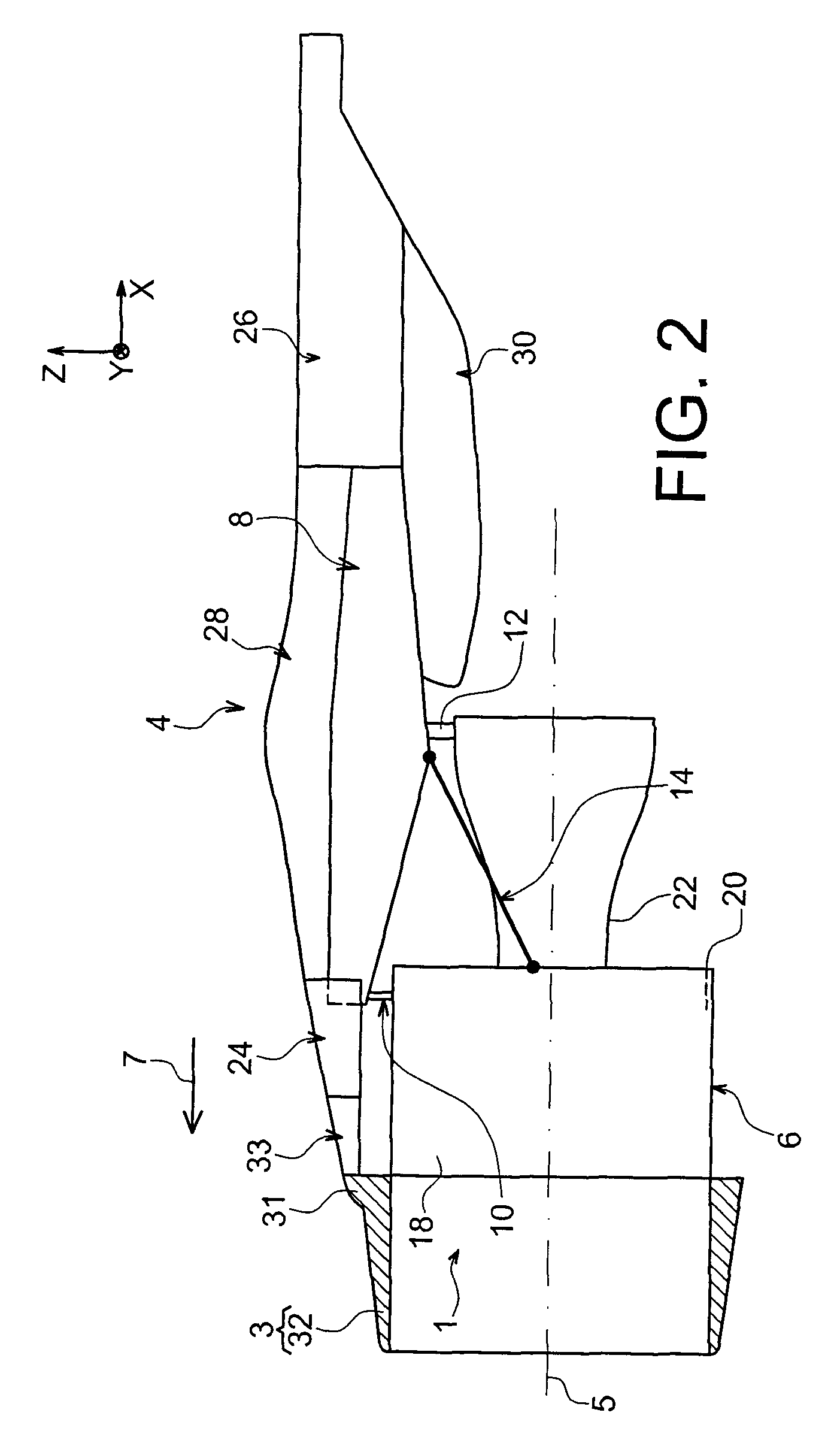
[0041]With reference first to FIGS. 1 and 2, an aircraft engine assembly 1 can be seen intended to be attached below a wing of this aircraft (not shown), this assembly 1 comprising an engine mounting structure 4, an engine 6 e.g. a turbojet engine hung from this mounting structure 4, and a nacelle 3 of which solely the front portion is shown in FIG. 1.

[0042]In the remainder of the following description, by convention X is used to designate the longitudinal direction of the mounting structure 4, which is comparable to the longitudinal direction of the turbojet engine 6, this direction X being parallel to a longitudinal axis 5 of this turbojet engine 6. Also Y is used to designate the direction oriented transversally relative to the mounting structure 4 and also comparable to the transverse direction of the turbojet engine 6, and Z designates the vertical direction or height, these three directions X, Y and Z lying orthogonal to each other.

[0043]Also, the terms > and > are to be consi...


PUM


Abstract

An aircraft engine assembly including an engine, an engine mounting structure, and a nacelle surrounding the engine and including an air intake and fan cowls. The assembly further includes a cradle supporting the fan cowls, fixedly mounted on the mounting structure or else on an entity including a fan case and the air intake attached to the case. The engine assembly further includes a junction aerodynamic fairing including a first mounting mechanism mounted on the cradle, and including a second mounting mechanism mounted on the other of the elements from among the mounting structure and the entity.

Description

TECHNICAL AREA[0001]The present invention generally relates to an aircraft engine assembly comprising an engine, an engine mount and a nacelle surrounding the engine the nacelle having an air intake and fan cowls, the above-mentioned engine mount possibly including a forward aerodynamic structure on which the fan cowls are movably mounted.[0002]This type of engine mount also called a mounting pylon or <<EMS>> for Engine Mounting Structure, globally allows an engine such as a turbojet engine to be attached below an aircraft wing, or to be mounted above this same wing, or even allows this same engine to be attached to an aft portion of the fuselage of the aircraft.STATE OF THE PRIOR ART[0003]Said mounting structure is effectively designed to form a connecting interface between an engine and an aircraft wing. It allows the loads generated by its associated engine to be transmitted to the airframe, and also provides a pathway for fuel and electric, hydraulic and air supply l...

Claims


Application Information

Patent Timeline
Patent Type & Authority Patents(United States)
IPC IPC(8): B64D27/00
CPCB64C7/02B64D29/08B64D2027/264
Inventor ROCHE, FREDERIC
Owner AIRBUS OPERATIONS (SAS)
Why Eureka
Try Eureka