Fan cowl support cradle mounted on the attachment pylon and on the air inlet of the nacelle

a technology of fan cowl and support cradle, which is applied in the direction of aircraft power plants, power plant construction, power plant types, etc., can solve the problems of affecting the overall performance of the aircraft, and affecting the global geometry of the unit, so as to reduce the space required and reduce the effect of aerodynamics

Active Publication Date: 2013-02-26
AIRBUS OPERATIONS INC AS A
View PDF12 Cites 1 Cited by
  • Summary
  • Abstract
  • Description
  • Claims
  • Application Information

AI Technical Summary

Benefits of technology

[0019]Consequently, the arrangement proposed makes it possible to greatly limit the harmful effects of misalignment described hereinabove, since the front portion of the cradle of the front aerodynamic structure carrying more preferably the fan cowls can now better accompany the displacements of the air inlet according to the deformations of the engine, during the periods of high stress on the unit.
[0020]As such, the flush junction between the air inlet of the nacelle and the fan cowls can be retained, which makes it possible to limit the losses of drag encountered with the realisations of prior art. In this respect, the losses of drag are also decreased by the retaining of the flush junction between the aerodynamic fairing and the other aerodynamic fairings of the attachment pylon, thanks to the presence of the rear means of hooking, likewise these losses of drag are also decreased by the retaining of the flush junction between the aerodynamic fairing and the air inlet, through the presence of the front means of hooking.
[0023]Moreover, even in the case of a loss of a fan blade, the front joint between the cradle and the air inlet implies that the risks of scooping between the front aerodynamic structure and the air inlet of the nacelle are strongly reduced, even reduced to nothing.
[0024]Finally, still due to the presence of the front joint between the cradle and the air inlet, the spaces required are greatly reduced, and in part are offset downstream, between the fairing of the cradle and the pylon, in a region that is less sensitive aerodynamically. Consequently, it is no longer advantageously required to provide the cradle with a system for adjusting, contrary to what was observed in prior art.
[0028]As such, the combination of the front fastener and of the two rear half-fasteners, constituting the set of means of hooking of the front aerodynamic structure, makes it possible to obtain means of hooking that are strongly advantageously close to an isostatic mounting system.

Problems solved by technology

However, when the engine unit is subjected to substantial stresses such as those encountered during the take-off and landing phases, or in flight during strong turbulence, the fixing of the cradle of the front aerodynamic structure to the rigid structure induces a substantial modification of the global geometry of the unit, and more specifically of that of the nacelle.
The phenomenon observed obviously caused the drag, which harms the overall performance of the aircraft.
Moreover, this solution consisting in connecting the cradle on the rigid structure of the attachment pylon causes its overhanging towards the front, which induces substantial mechanical stresses due to the associated mass.
In addition, when the cradle is mounted on the fan case of the engine, this normally causes difficulties in demonstrating the resistance of the front aerodynamic structure to the fan blade loss phenomenon, phenomenon also referred to as “Fan Blade Out”, in that the front aerodynamic structure mounted fixedly on the fan case undergoes the same accelerations / displacements as the latter.
In order to respond to these difficulties, it may as such be required to carry out van impact resistance tests with the cradle mounted on the fan case, this type of test is currently however not very well mastered.
On the other hand, with this technical solution for mounting, a fan blade loss can result in substantial risks of scooping between the front aerodynamic structure and the air inlet of the nacelle.
Indeed, subsequent to the impact observed during a blade loss, a major displacement propagates in a few milliseconds on the fan case.
These same spaces, if they do not close back up, can increase in size very rapidly, and therefore cause the loss of the front aerodynamic structure, as well as that of the fan cowls.
This system has the disadvantages of being costly as well as taking up much space.

Method used


Image

  • Fan cowl support cradle mounted on the attachment pylon and on the air inlet of the nacelle
  • Fan cowl support cradle mounted on the attachment pylon and on the air inlet of the nacelle
  • Fan cowl support cradle mounted on the attachment pylon and on the air inlet of the nacelle

Examples


Embodiment Construction

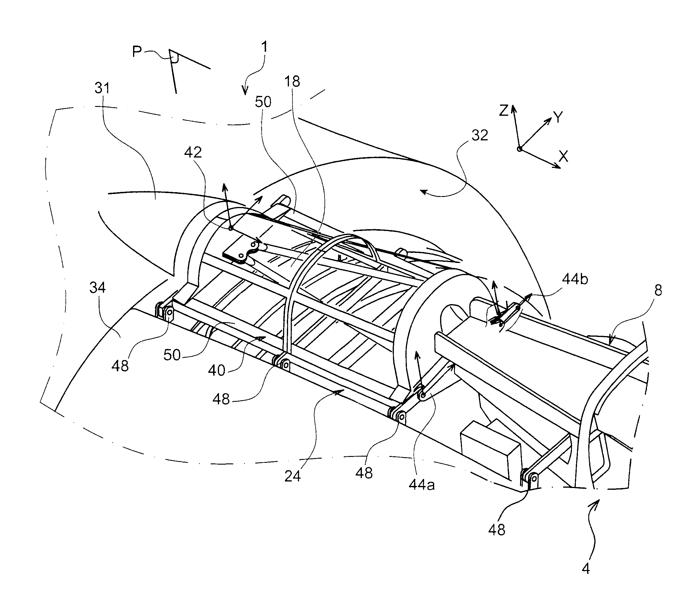
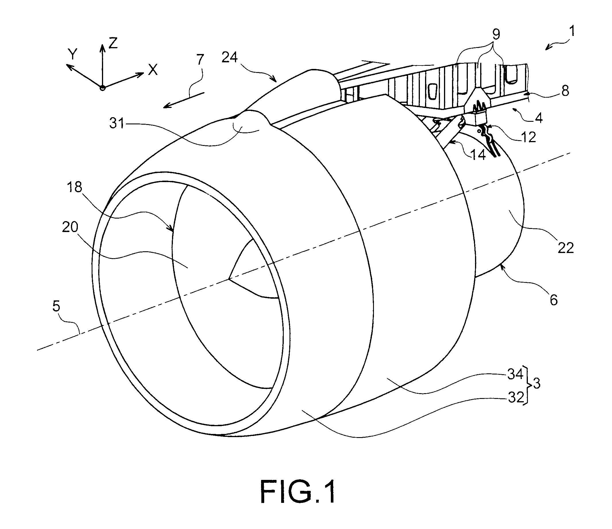
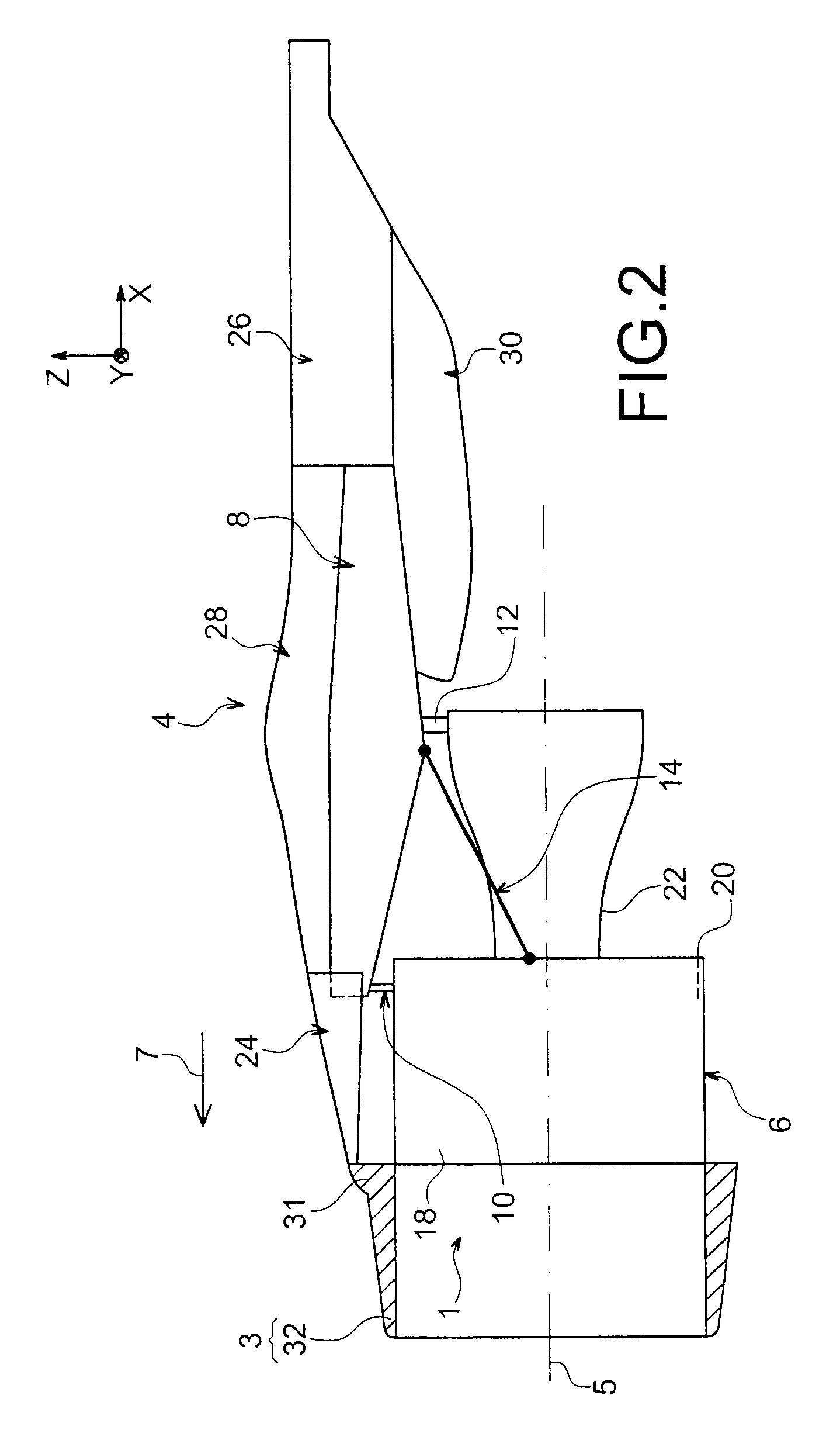
[0048]In reference first of all to FIGS. 1 and 2, an engine unit 1 for aircraft is shown intended to be fixed under a wing of this aircraft (not shown), this unit 1 comprising a device for hooking 4, an engine 6 such as a jet engine fastened under this device 4, and a nacelle 3 of which only the front portion has been shown in FIG. 1.

[0049]In all the description which shall follow, by convention, X shall refer to the longitudinal direction of the device 4 which is also similar to the longitudinal direction of the jet engine 6, this direction X being parallel to a longitudinal axis 5 of this jet engine 6. On the other hand, Y refers to the direction directed transversally in relation to device 4 and also similar to the transversal direction of the jet engine 6, and Z the vertical direction or of the height, these three directions X, Y and Z being orthogonal to each other.

[0050]On the other hand, the terms “front” and “rear” are to be considered in relation to a forward direction of t...


PUM


Abstract

An engine unit for an aircraft including an engine, a device for hooking the engine, and a nacelle surrounding the engine and provided with fan cowls, the device for hooking including a rigid structure and a front aerodynamic structure whereon the fan cowls are articulated, the front aerodynamic structure including a cradle with a rear mechanism of hooking mounted on the rigid structure. The cradle also includes a front mechanism of hooking mounted on an air inlet of the nacelle.

Description

TECHNICAL FIELD[0001]This invention in general relates to an engine unit for aircraft comprising an engine, a device for hooking the engine as well as a nacelle surrounding the engine and provided with fan cowls as well as an air inlet, the aforementioned device for hooking comprising a rigid structure as well as a front aerodynamic structure whereon the fan cowls are articulated.[0002]This type of device for hooking, also called an attachment pylon or “EMS” (“Engine Mounting Structure”), globally makes it possible to suspend an engine such as a engine below the wing of the aircraft, or to mount this engine above this same wing, or to assemble this engine on a rear portion of the fuselage of the aircraft.PRIOR ART[0003]Such a device for hooking is indeed provided to comprise the connection interface between an engine and a wing of the aircraft. It makes it possible to transmit to the structure of this aircraft the loads generated by its associated engine, and also allows for the rou...

Claims


Application Information

Patent Timeline
Patent Type & Authority Patents(United States)
IPC IPC(8): B64D27/16
CPCB64D27/18B64D27/26B64D2027/264
Inventor DUSSOL, LOICRIDRAY, FREDERIC
Owner AIRBUS OPERATIONS INC AS A
Why Eureka
Try Eureka