
Metal-resin compound member

a technology of metal-resin and compound parts, which is applied in the direction of electrical apparatus casings/cabinets/drawers, coupling device connections, transportation and packaging, etc., can solve the problems of complex mold and injection molding process configuration, and high joint strength, and high reliability

Active Publication Date: 2013-01-22
NGK SPARK PLUG CO LTD
View PDF47 Cites 14 Cited by
  • Summary
  • Abstract
  • Description
  • Claims
  • Application Information

AI Technical Summary

Benefits of technology

This approach simplifies the molding process, reduces manufacturing costs, and enhances the design flexibility of resin structures while maintaining high joint strength and reliability, allowing for complex shapes and configurations.

Problems solved by technology

Therefore, the configuration of each mold and the process of injection molding become complicated.
That is, when manufacturing the metal-resin composite body having the above configuration, the configuration of the mold and the process of the injection molding become complicated in the case where the connector 11 that is the resin structure is integrated with the case main body 2 that is the metal component by injection molding.
As the shape and the configuration of the connector 11 that is the resin structure and those of the case main body 2 that is the metal component are complicated, the structure of the mold and the process of injection molding become complicated.
(1) Manufacturing the mold is costly due to a complication of the mold structure, such as a slide core.
(2) The complicated mold leads to a complication of molding process and work, resulting in deterioration in a manufacturing efficiency. Therefore, the cost of the injection molding of the resin structure or the manufacturing cost of the metal-resin composite body rise.
(3) When the structure of the mold becomes complicated, a gap between the molds and / or between the mold and a closing face of a metal component (insert article) is likely to be formed. Thus, a defect, such as a burr (excessive resin), is likely to occur.
(4) Limitations on a shape of resin structure and on its structural design are required due to the reasons stated above (1)˜(4). Therefore, suitable shape and structure of the resin structure may not be materialized. That is, the degree of design freedom of the resin structure is low.

Method used


Image

  • Metal-resin compound member
  • Metal-resin compound member
  • Metal-resin compound member

Examples


Embodiment Construction

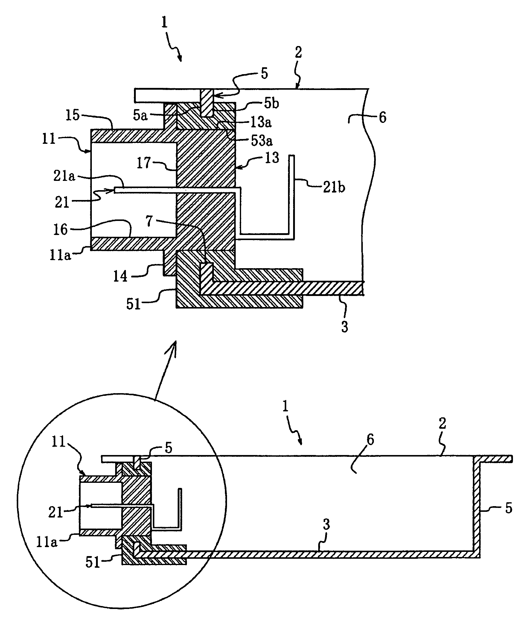
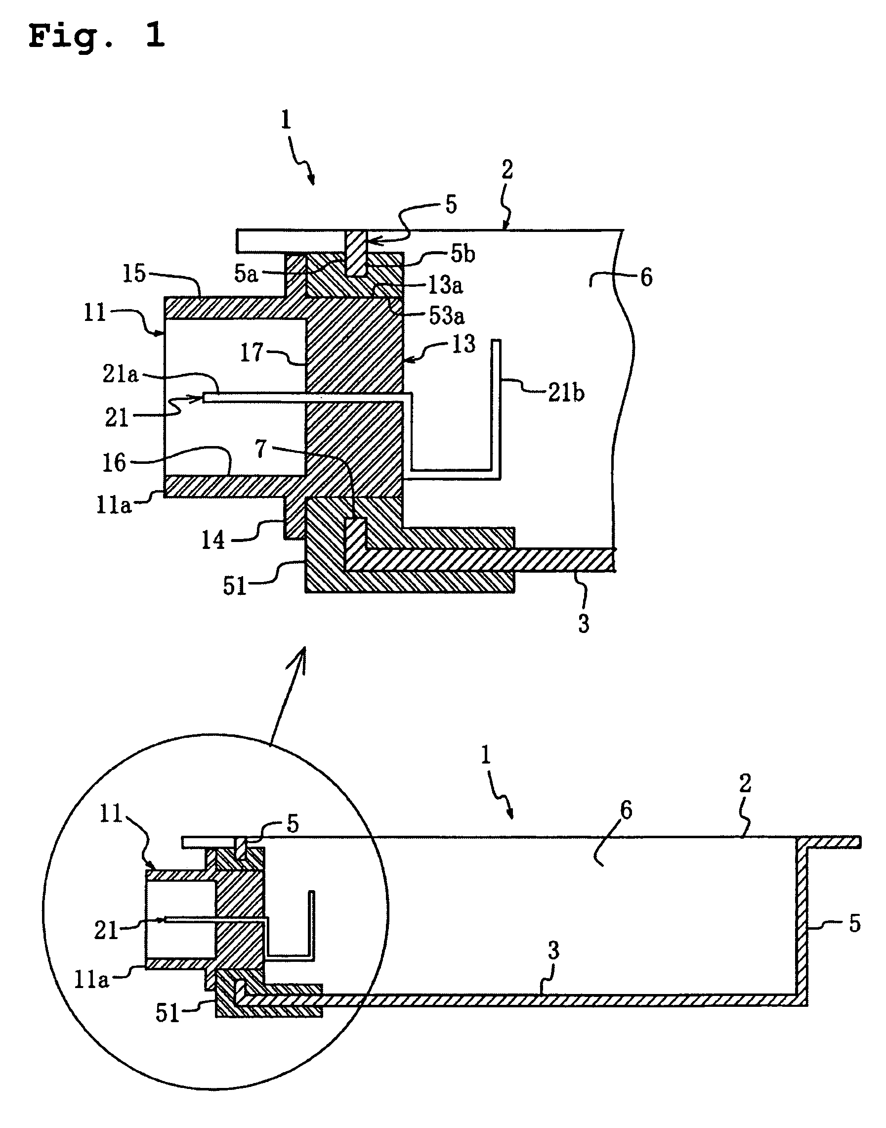
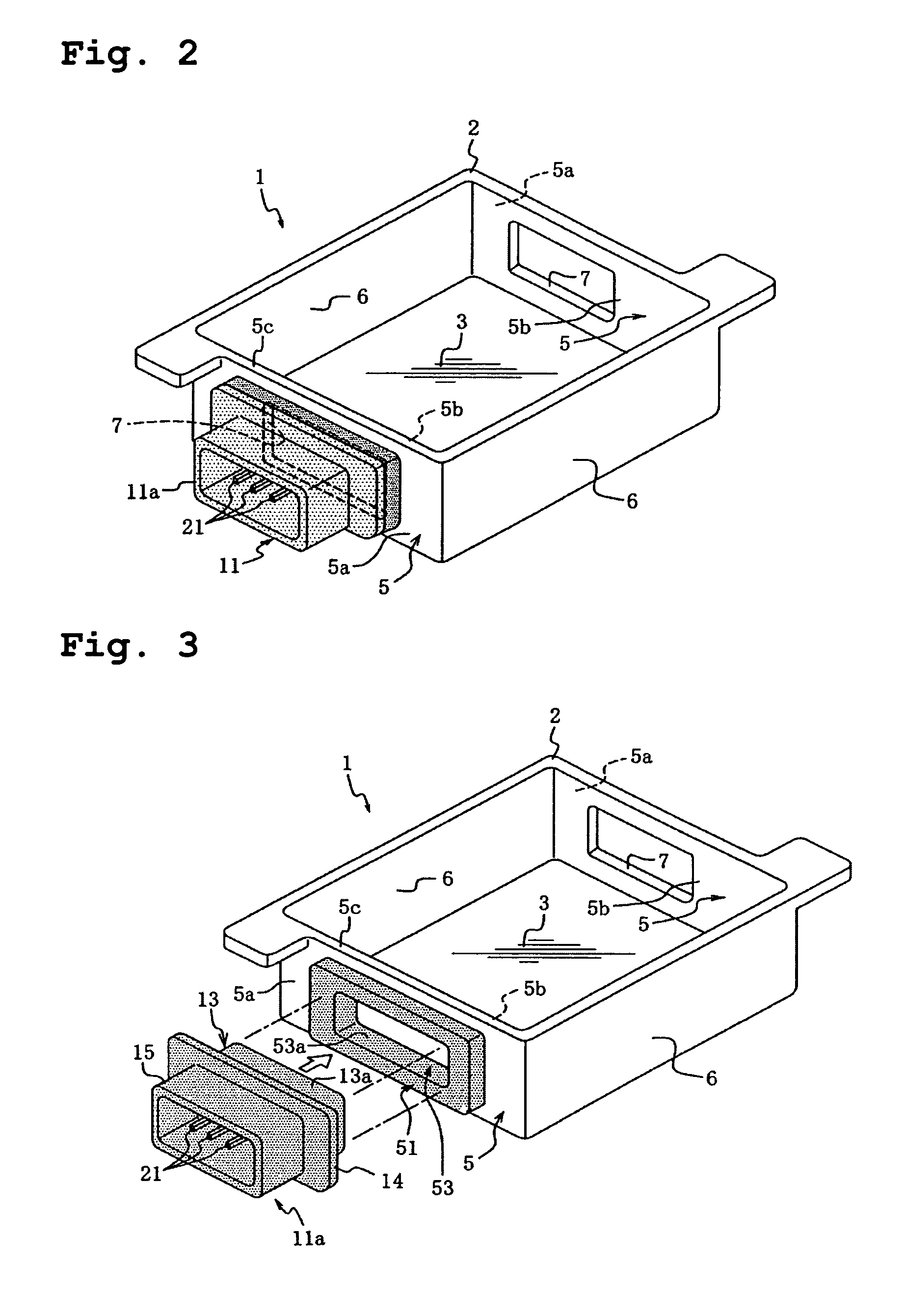
[0043]An embodiment of the invention will now be described in detail with reference to the drawings 1 to 4. In this embodiment, a metal-resin composite body serves as a case 1 with a connector used for housing a wiring board, a metal component serves as a case main body, and a resin structure serves as a connector as described in the background of the invention. This metal-resin composite body (hereinafter simply referred to as a composite body) has basically the same configuration as the conventional art in FIG. 8. That is, the reference numeral “1” is the case with connector used for housing a wiring board which is the metal-resin composite body. The reference numeral “2” is the metal case main body that is a metal component and made of an aluminum, a zinc, a magnesium, or an alloy thereof. The metal case main body 2 assumes a rectangular parallelepiped shape (a tray-shape) formed by a press molding or a die-casting. Side walls 5, 6 rising from a bottom wall 3 of the case main bod...


PUM

PropertyMeasurementUnit
shapeaaaaaaaaaa
structureaaaaaaaaaa
resin structureaaaaaaaaaa

Abstract

A case comprised of a metal-resin composite body having a connector including a terminal fitting, the connector being integrated with an opening of a wall of a case main body so that the connector sandwiches an edge of the wall. The connector is comprised of a base resin formed by injection molding so as to sandwich the wall. A separately-manufactured connector is welded to the base resin. Forming the base resin on the case main body provides a less complicated configuration of the case compared to a case where a connector is formed directly to the case main body.

Description

FIELD OF THE INVENTION[0001]The present invention relates to a metal-resin composite body in which a metal component is integrated with a resin structure of a predetermined shape or a resin structure including therein a conduction path component, such as a terminal fitting and an electric wire.BACKGROUND OF THE INVENTION[0002]As an example of a metal-resin composite body, FIG. 8 shows a case 1 with a connector 11 used for housing a wiring board (hereinafter referred to as a case with a connector or simply a case) in which the connector 11 that is a resin structure is integrated with a case main body 2 (also referred to as a case main body) used for housing a wiring board. The case main body 2 is a metal component and assumes a rectangular parallelepiped tray shape. The connector 11 is integrated with an opening portion 7 of a side wall 5 (simply referred to as a wall 5) formed around a bottom wall (bottom plate) 3 of the case main body 2. FIG. 8 is a general structural perspective v...

Claims


Application Information

Patent Timeline
Patent Type & Authority Patents(United States)
IPC IPC(8): H05K7/14
CPCB29C45/14311B29C45/14639B29C45/14778H01R13/405B29C45/006B29C33/44Y10T428/19B29C65/04B29C65/08B29C65/16B29C65/48B29C66/54B29K2305/00B29K2705/00B29L2031/3061B29L2031/3481H01R13/74H01R43/0221B29C66/53461H01R13/6599H05K5/0069Y10T428/31678Y10T428/24996
Inventor KOHMURA, YOSHIHIKOYOSHIDA, SHINGOFUJI, YUSUKEHIRAI, TAKAYAKAWAGISHI, WATARU
Owner NGK SPARK PLUG CO LTD
Learn More