Bicycle disk brake apparatus with laminated components

a technology of brake apparatus and disc brake, which is applied in the field of bicycles, can solve the problems of rotors suffering from separation of the rotor main body and the braking face member, and achieve the effect of greater braking wear resistan

Active Publication Date: 2013-02-05
SHIMANO INC
View PDF19 Cites 14 Cited by
  • Summary
  • Abstract
  • Description
  • Claims
  • Application Information

AI Technical Summary

Problems solved by technology

However, such rotors suffer from separation of the braking face member from the rotor main body despite the metal interlayer between them.

Method used


Image

  • Bicycle disk brake apparatus with laminated components
  • Bicycle disk brake apparatus with laminated components
  • Bicycle disk brake apparatus with laminated components

Examples


Embodiment Construction

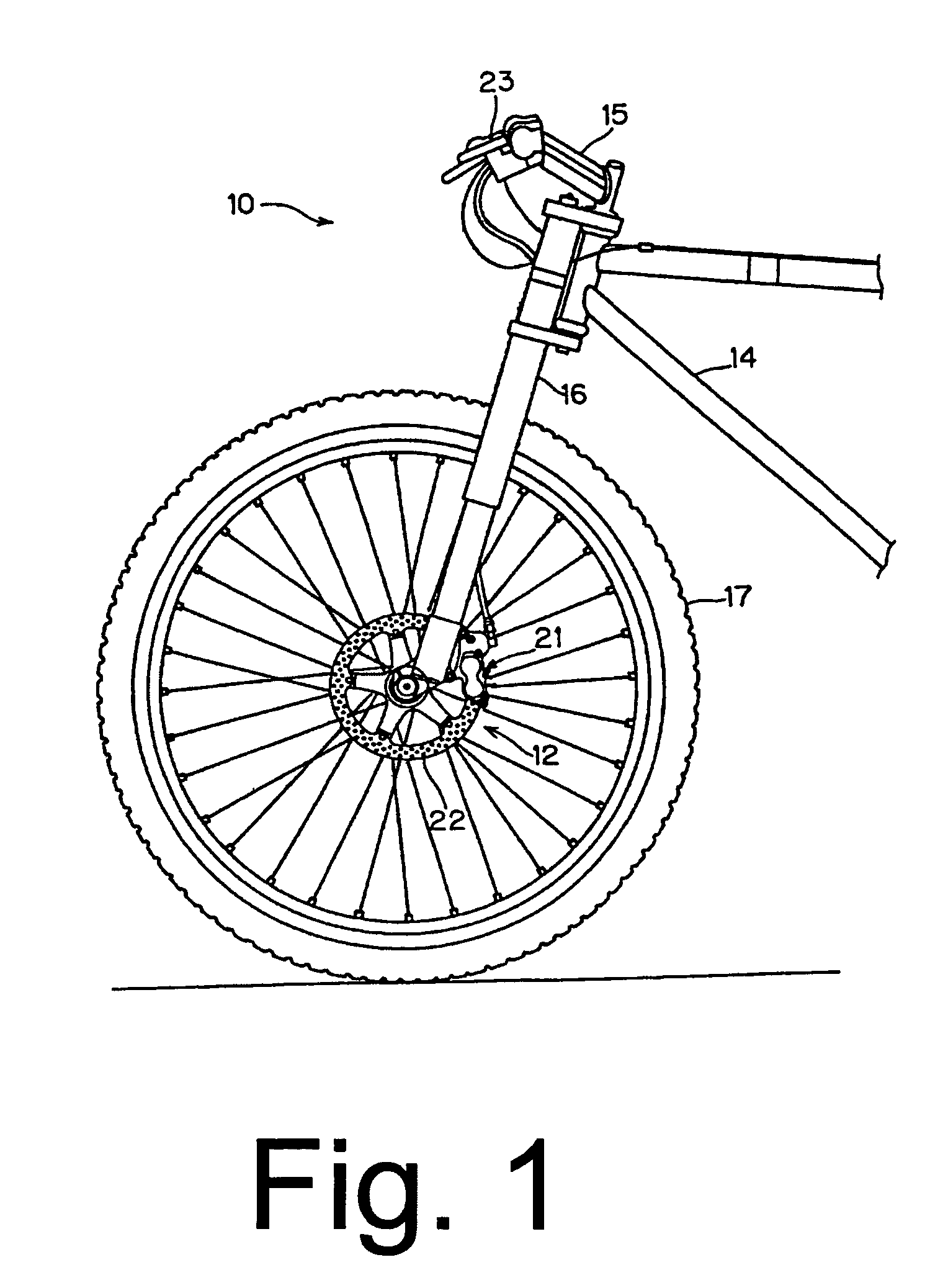
[0015]FIG. 1 is a side view of a bicycle 10 with a particular embodiment of a complete disk brake apparatus 12. Bicycle 10 is a conventional one with a frame 14 supporting a handlebar 15, front and rear forks 16 (only the front fork is shown), front and rear wheels 17 (only the front wheel is shown), and a drive device comprising a sprocket and chain (not shown). Since the structure of such a conventional bicycle is well known in the field, further description if its structure shall be omitted.

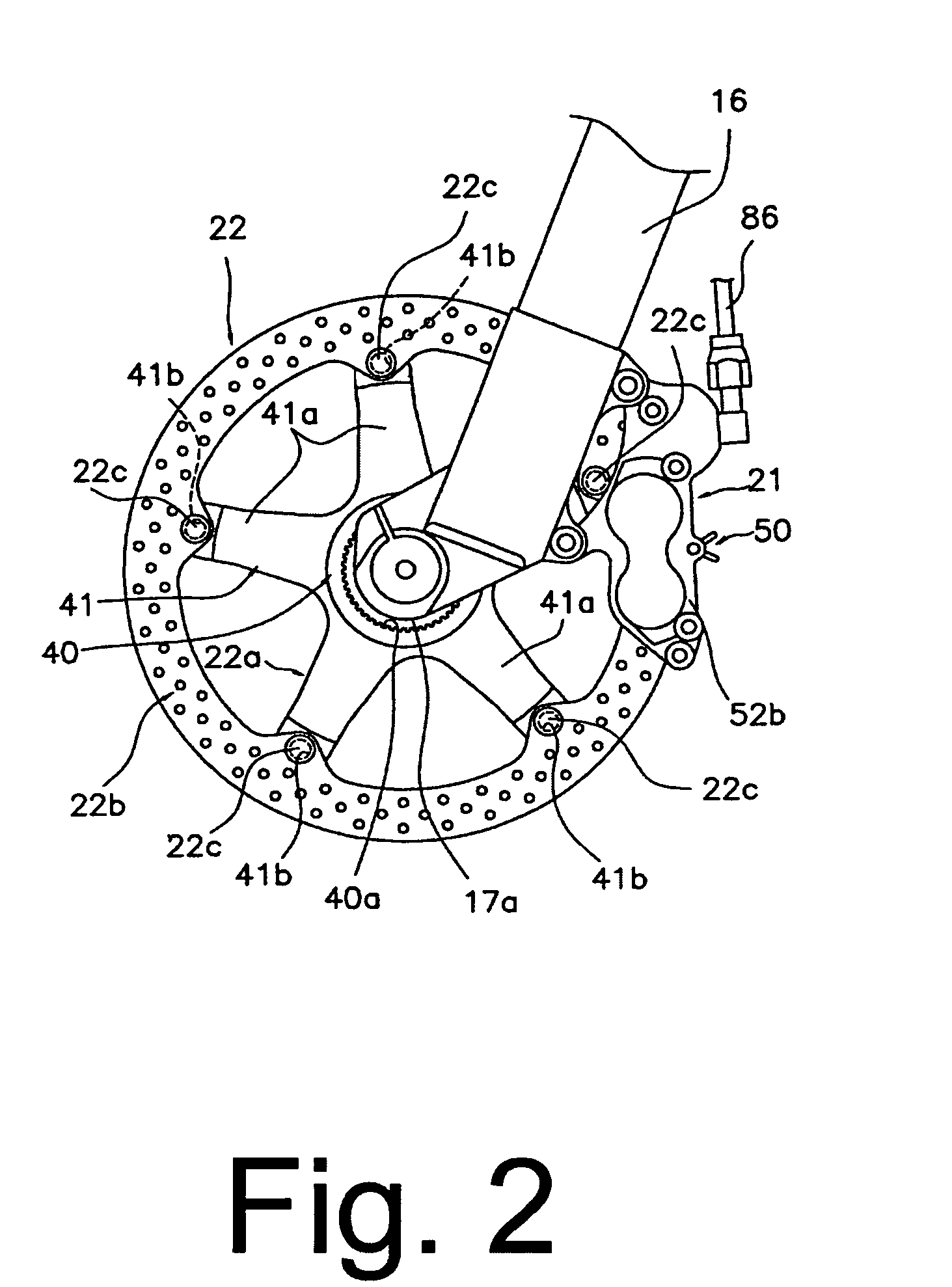
[0016]Disk brake apparatus 12 comprises a brake caliper 21 mounted on front fork 16, a brake rotor 22 attached to a hub 17a of front wheel 17 so that brake rotor 22 rotates integrally with front wheel 17, and a brake operating mechanism 23. Brake caliper 21 is attached to front fork 16 near brake rotor 22, and it applies a frictional force to brake rotor 22 in response to the operation of brake operating mechanism 23 to stop the rotation of brake rotor 22 and front wheel 17.

[0017]As shown in F...


PUM


Abstract

A bicycle disk brake rotor apparatus comprises a generally circular first rotor member and a generally circular first second rotor member. The first rotor member has a first fixing component structured to mount the first rotor member to a hub mounting member, and the first second rotor member has a first fixing component structured to mount the first second rotor member to the hub mounting member. The first rotor member is attached to a side of the first second rotor member, and the first second rotor member is formed of a material having greater braking wear resistance than the first rotor member.

Description

BACKGROUND OF THE INVENTION[0001]The present invention is directed to bicycles and, more particularly, to a bicycle disk brake apparatus.[0002]Conventional bicycle disk brake devices comprise a disk rotor that rotates with the bicycle wheel, and calipers with brake pads that frictionally contact the disk rotor to slow or stop the wheel. The disk rotor may be a metal member that comprises a mounting member and a ring-shaped rotor member fixed to the mounting member, wherein the mounting member is structured to be mounted to the bicycle wheel hub. Since bicycles are propelled by human power, reducing the weight of the bicycle components is an important objective of many bicycle manufacturers. This includes reducing the weight of disk brake devices. On the other hand, it is also desirable to resist rotor wear caused by friction with the brake pads while providing proper heat dissipation.[0003]One example of a conventional disk rotor that is lightweight and has good heat dissipation and...

Claims


Application Information

Patent Timeline
Patent Type & Authority Patents(United States)
IPC IPC(8): F16D65/12B62L1/00
CPCB62L1/005F16D65/123F16D65/128F16D2065/132F16D2065/1356F16D2065/1392F16D2200/0017F16D2200/003
Inventor IWAI, TORUFUJITANI, TAKASHITSUBOUCHI, KENJI
Owner SHIMANO INC
Why Eureka
Try Eureka