Supercharge Your Innovation With Domain-Expert AI Agents!

Caster with dual offset orbital mounting assembly

a technology of mounting assembly and caster, which is applied in the field of casters, can solve the problems of greater rolling resistance, wear of the wheel, and inability to easily turn about the pivot poin

Active Publication Date: 2013-03-05
AUBIN PHILIP A
View PDF14 Cites 6 Cited by
  • Summary
  • Abstract
  • Description
  • Claims
  • Application Information

AI Technical Summary

Benefits of technology

[0011]The present invention generally comprises a caster assembly that enables the caster wheel to easily align itself with the direction of thrust applied to a caster-supported object. This advantageous feature is made possible by providing a dual pivot assembly in the caster mounting that is laterally offset, whereby the caster wheels may not only pivot about a wheel pivot axis that extends through the plane of the caster wheel, but also revolve orbitally about a mounting pivot axis that is laterally offset from the wheel axis. As a result, the caster assembly easily may assume the proper orientation for any thrust applied to the caster-supported object, whereby caster “lock-up” is eliminated.
[0013]The other bearing assembly supports a cylindrical head post that extends to a clevis-like bracket that straddles a wheel and supports at the clevis ends an axle for the wheel, as is known in the prior art. The clevis has a head angle that is typical for a caster wheel, and the wheel is free to rotate about the axis of the head post, which in turn is supported by the transfer plate, which itself is rotatable about the axis of the mounting tube. Thus the caster wheel may roll on its axle on a floor surface, and revolve about the pivot axis of the head post, and also rotate orbitally about the axis of the mounting tube. These three axes of movement enable the caster wheel easily to move into the proper alignment for any thrust applied to the object supported by the caster. Indeed, if the caster is “locked up”, that is, transverse to the thrust on the object, the object appears to pivot about the locked up wheel, using the orbital motion of the transfer plate, until the thrust vector more closely aligns with the wheel direction, after which the wheel may pivot into aligned orientation with the thrust vector.

Problems solved by technology

The main problem of the ‘single wheel’ caster is its inability to turn easily about the pivot.
The result is wear of the wheel and greater rolling resistance at low speeds and tight turns, and most particularly high rolling resistance during startup from zero velocity.
A narrower wheel minimizes this problem, but results in greater pressure (force per unit area) applied to the floor surface.
One problem germane to this caster type is the method of attachment of the wheel to the axle.
The wheels and the ends of the shaft are relatively unprotected and vulnerable to impact, which can result in collision-damaged wheels or a bent axle.
This attachment configuration also creates some inherent stability inefficiencies.
Also, the limited space remaining in the device for the wheel thickness results in thin wheels, which directly result in narrow annular (limited) bearing surfaces of the wheel on the axle.
The twin wheel design is typically limited to use in office furniture, where the loads are lighter and the objects are not often moved.
A problem that is common to single wheel and twin wheel casters is that the casters can become “locked up” when at least two casters supporting a wheeled object are pivoted to extend in directions that are substantially misaligned with each other.
For example, if a cart with four swiveling (pivoting) casters is pushed toward a wall and abutted against the wall surface, it may then become difficult to slide the cart along the wall to reposition it, due to the fact that the casters are misaligned with respect to the plane of the wall surface.
The result is that objects supported by casters may be difficult to start to roll in a desired direction if that direction does not align with the casters.

Method used


Image

  • Caster with dual offset orbital mounting assembly
  • Caster with dual offset orbital mounting assembly
  • Caster with dual offset orbital mounting assembly

Examples


Embodiment Construction

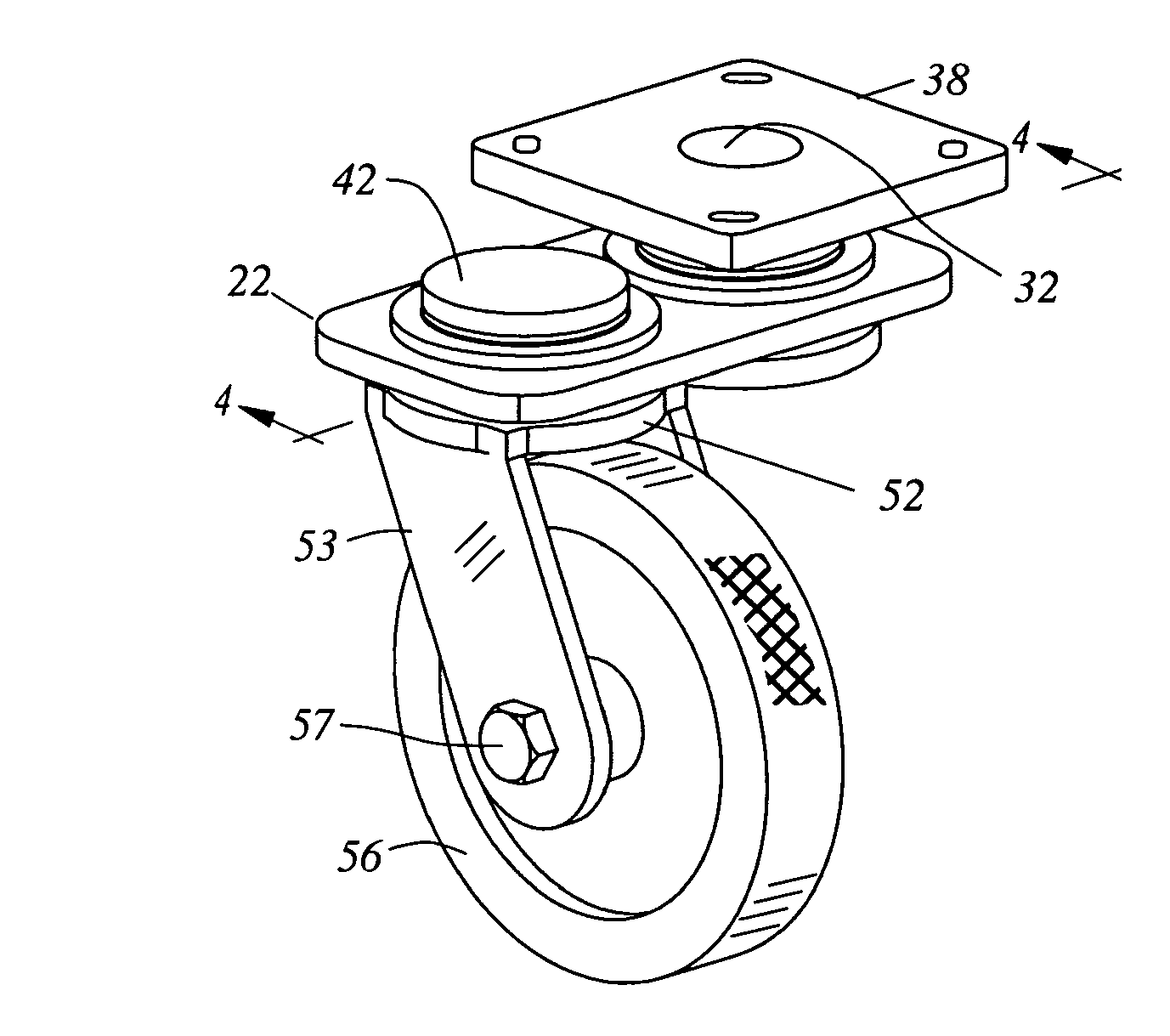
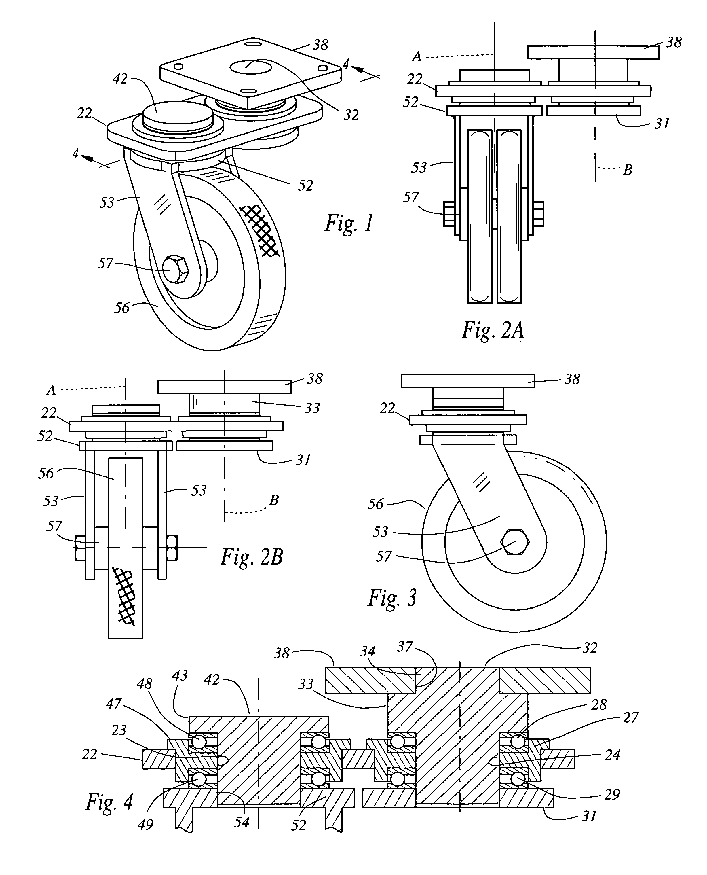
[0022]The present invention generally comprises a caster assembly that enables the caster wheel to easily align itself with the direction of thrust applied to a caster-supported object. With regard to FIGS. 1-3 and 9, the caster assembly 21 is composed of a transfer plate 22, which is a high strength plate (steel or the like) having two cylindrical openings 23 and 24 extending along adjacent, generally parallel axes A and B respectively. A mounting bearing assembly 26 includes a bearing housing tube 27 that is pressed into the opening 24 and supports upper and lower ball bearing races 28 and 29. A mounting post 32 has an annular shoulder 33 that defines an upper end 34. The upper end 34 of the post 32 is received in an opening 37 of a mounting plate 38. Note that the end 34 may be pressed in the opening 37 or welded thereat, and that the annular shoulder 33 is abutting the surface of the plate 38 to form a wide engagement that prevents any movement of the post 32. It may be apprecia...


PUM


Abstract

A caster assembly has a dual pivot assembly in the caster mounting that is laterally offset, whereby the caster wheels may not only pivot about a wheel pivot axis that extends through the plane of the caster wheel, but also revolve orbitally about a mounting pivot axis that is laterally offset from and parallel to the wheel axis. A transfer plate supports a pair of bearing assemblies, one of them securing a mounting post secured to the bottom of an object. The other bearing assembly supports a cylindrical head post that extends to a clevis-like bracket that supports a caster wheel.

Description

CROSS-REFERENCE TO RELATED APPLICATIONS[0001]This application claims the priority benefit of the filing date of Provisional Application No. 61 / 374,700, filed Aug. 18, 2010.FEDERALLY SPONSORED RESEARCH[0002]Not applicable.SEQUENCE LISTING, ETC ON CD[0003]Not applicable.BACKGROUND OF THE INVENTION[0004]1. Field of the Invention[0005]This invention relates to casters and, more particularly, to caster assemblies that allow the caster to pivot easily to accommodate the direction of thrust applied to an object supported by the caster.[0006]2. Description of Related Art[0007]Caster designs tend to fall into one of two groups: the ‘single wheel’ and the ‘twin wheel’. The single wheel caster consists of one wheel with an axle through the center which is attached to a clevis-like bracket that supports the axle at opposed ends. The bracket is joined to a bearing assembly that allows the caster to pivot about a generally vertical axis while also permitting rotation of the wheel about a generall...

Claims


Application Information

Patent Timeline
Patent Type & Authority Patents(United States)
IPC IPC(8): B60B33/00
CPCB60B33/0015B60B33/0018B60B33/0039B60B33/0042B60B33/0049B60B33/0073B60B33/0076B60B33/0057Y10T16/186Y10T16/1847Y10T16/203Y10T16/1857
Inventor AUBIN, PHILIP A.
Owner AUBIN PHILIP A
Features
  • R&D
  • Intellectual Property
  • Life Sciences
  • Materials
  • Tech Scout
  • Unparalleled Data Quality
  • Higher Quality Content
  • 60% Fewer Hallucinations
Learn More