Universal quick-mounting, no bolts gunsight mount

a gun mount and bolt-free technology, applied in the field of universal quick-mounting gunsight mounts, can solve the problems of mounting slipping, non-repeatability of sight mount accuracy, and difficulty in achieving the correct tightness and equal tightness of bolts without using a torque wrench

Active Publication Date: 2013-03-12
WILSON BRIAN
View PDF7 Cites 21 Cited by
  • Summary
  • Abstract
  • Description
  • Claims
  • Application Information

AI Technical Summary

Benefits of technology

[0006]The present invention relates to a universal, quick-mount gunsight mount that does not require any bolts. The mount fits any pistol that has Picatinny Rail mount and / or a light rail mount or laser mount on the lower muzzle. The mount of the invention is a single piece that slips around the muzzle. The device has two jaws with a mating top part that start in a slightly separated position to allow the unit to be slipped onto the muzzle. A protrusion on each side mates into the slots above the Picatinny Rail on the gun. A spring-loaded detent is slipped into the mount under the muzzle which, in a locked position, forces a member into a slot in the Picatinny Rail on the bottom of the rail. A scope sight is then clamped onto the top of the mount. The clamping of the sight causes the two jaws to pull together and tightly mate. This also causes the protrusions on the bottom to fit snugly into and along the slots formed by the Picatinny Rail. The mount thus becomes locked and will not move when the gun is fired. The bottom of the mount includes an optional rail that can be used for a laser or light. When used, these accessories do not have to be removed when the mount is removed. The mechanical sights supplied with the gun are not blocked by the mount of the present invention and can be used when desired.

Problems solved by technology

In all these units, it is very difficult to achieve the correct tightness and equal tightness of the bolts without using a torque wrench.
If the bolts are not correctly tightened, or equally tight in multi-bolt units, the mount can be offset either left or right causing non-repeatability in the sight mount accuracy on the same pistol, or the mount can slip when the gun is fired.

Method used


Image

  • Universal quick-mounting, no bolts gunsight mount
  • Universal quick-mounting, no bolts gunsight mount
  • Universal quick-mounting, no bolts gunsight mount

Examples


Embodiment Construction

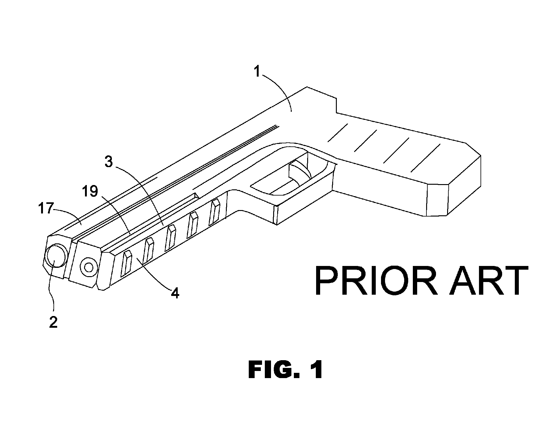
[0014]The present invention relates to a universal gunsight mount for pistols have Picatinny Rails or other types of longitudinal grooves along the muzzle. FIG. 1 shows a prior art pistol with on mount. The pistol 1 has a barrel 2 emerging from the muzzle 17. A Picatinny Rail 3 runs longitudinally along the bottom of the muzzle 17 forming a longitudinal groove 19. Also, there may be slots 4 for bolts on the bottom of the Picatinny Rail 3.

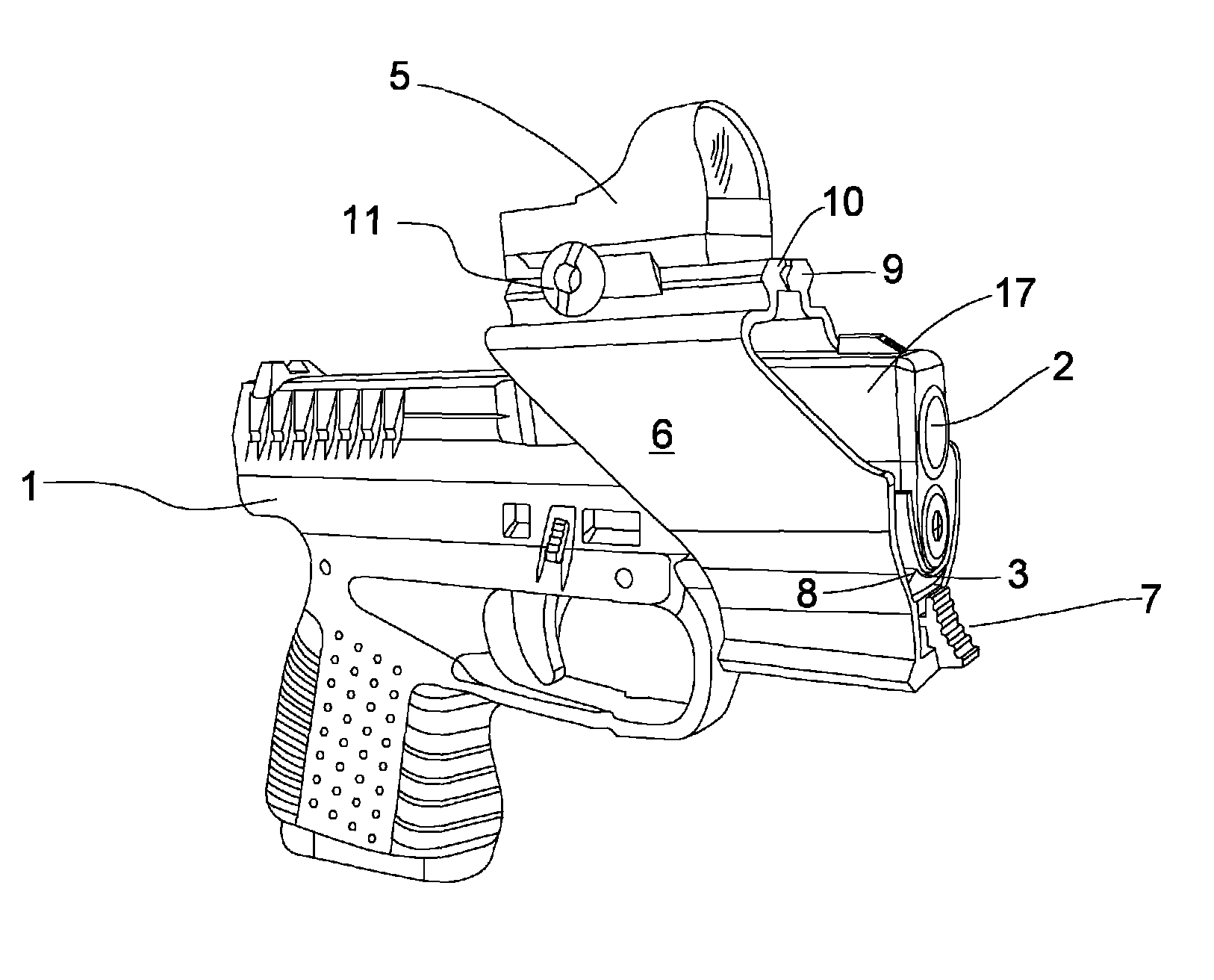
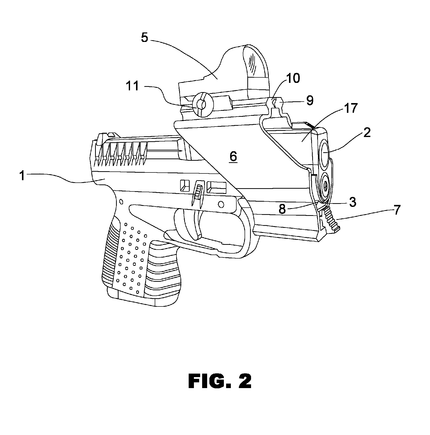
[0015]FIG. 2 shows a front and side perspective view of a pistol 1 with an embodiment of a mount with jaws 6 fully mounted with a scope sight 5. Just below the front bottom of the muzzle 17, a protrusion 8 that is part of the mount mates into the slot formed by the Picatinny Rail 3. A spring-loaded detent 7 has been inserted into the mount jaws 6 from the front just under the bottom of the muzzle 17. The detent 7, in a locked position, forces a solid member up into the bolt slot in the Picatinny Rail 3 securing the jaws 6 to the gun. The scope sight...


PUM


Abstract

A universal, quick-mount gunsight mount that does not require any bolts. The mount fits any pistol that has Picatinny Rail or that has any longitudinal groove on the lower muzzle. The mount includes a single piece that slips around the muzzle with two jaws that mate at the top when a sight is clamped on. A protrusion on each side of the mount mates into the slot formed by the Picatinny Rail on the gun, while a detent forces a member into a slot on the bottom of the muzzle. The mount becomes locked to the muzzle and will not move when the gun is fired. The bottom of the mount includes an optional rail that can be used for a laser or light. The mechanical sights supplied with the gun are not blocked and can be used when desired.

Description

BACKGROUND[0001]1. Field of the Invention[0002]The present invention relates to mounting accessories for guns and more particularly to a universal quick-mounting gunsight mount that does not require bolts.[0003]2. Description of the Prior Art[0004]Gunsight mounts for pistols are known in the art. All mounts made today are clamp assemblies that are bolted around the barrel of the gun. Most slip over the muzzle of the gun and are bolted at the bottom, the top or both. Some units are two-piece assemblies with a bolt on top and a bolt on the bottom, or slip-over assemblies with a single bolt on the bottom. Some units have two bolts on the top and two bolts on the bottom. In all these units, it is very difficult to achieve the correct tightness and equal tightness of the bolts without using a torque wrench. If the bolts are not correctly tightened, or equally tight in multi-bolt units, the mount can be offset either left or right causing non-repeatability in the sight mount accuracy on t...

Claims


Application Information

Patent Timeline
Patent Type & Authority Patents(United States)
IPC IPC(8): F41G1/387
CPCF41G11/003
Inventor WILSON, BRIAN
Owner WILSON BRIAN
Why Eureka
Try Eureka