
Wireless communication tag and wireless communication system

a wireless communication and tag technology, applied in the direction of digital computer details, instruments, digital output to print units, etc., can solve the problems of inconvenient use, inconvenient use, and inability to supply active-type communication tags, so as to increase the communication distance and efficiently supply the

Active Publication Date: 2013-03-19
MYCLERK LLC
View PDF9 Cites 3 Cited by
  • Summary
  • Abstract
  • Description
  • Claims
  • Application Information

AI Technical Summary

Benefits of technology

The present invention provides a way to generate electricity at a low cost and store it in a charging unit using a separate antenna that receives electromotive radio waves. This stored energy can be used at a later time to communicate with a reader / writer, even in different environments. This results in a low-cost wireless communication tag and system that can increase the distance between the tag and reader / writer, ensuring stable communication.

Problems solved by technology

The active-type communication tag is not only costly, but also requires battery discarding or replacement at cycle of several years because the battery must be loaded.
With the conventional wireless communication tag of the passive type as described above, a communication distance is undesirably limited according to the amount of power charge when the tag communicates the ID (identification information) with the reader / writer.
In the above-described art proposed in Japanese Laid-open Patent Publication No. 2007-34951, however, a configuration for connecting the commercially available power source must be additionally set up, thus resulting in a complicated wireless communication tag structure and high manufacturing cost.
Furthermore, with this art, a condition for using the wireless communication tag is limited under an environment where the commercially available power source can be ensured, so that a certain limitation is undesirably imposed on an environment of using this wireless communication tag.

Method used


Image

  • Wireless communication tag and wireless communication system
  • Wireless communication tag and wireless communication system
  • Wireless communication tag and wireless communication system

Examples


Embodiment Construction

[0041]Hereinafter, a wireless communication tag and a wireless communication system, according to a first embodiment of the present invention, will be described with reference to the accompanying drawings.

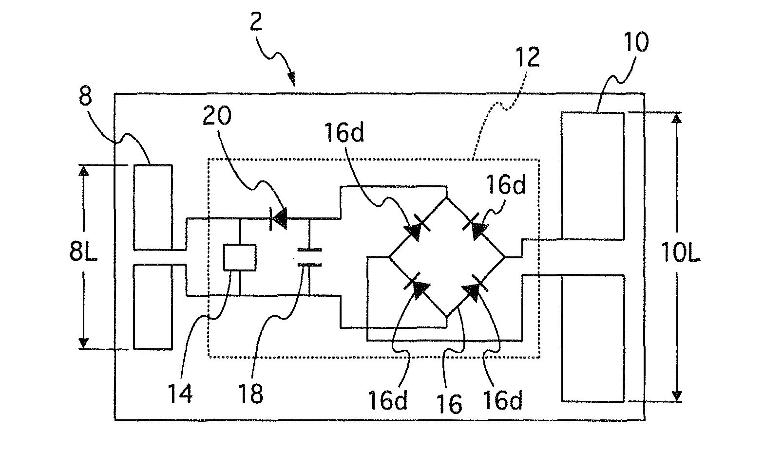
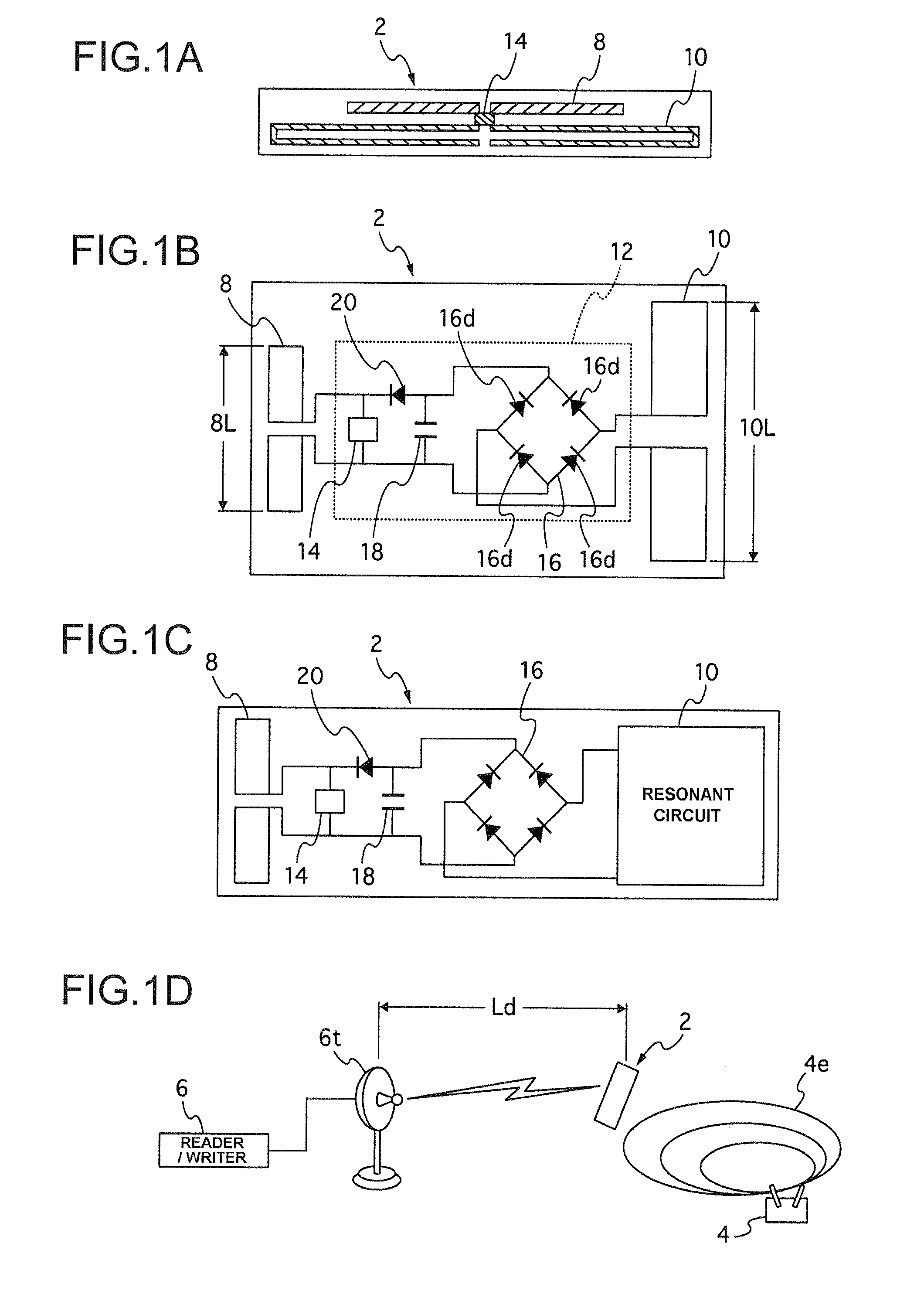
[0042]This embodiment assumes a wireless communication tag of the passive type, in which electric power is generated by a radio wave. The wireless communication tag 2, as shown in FIG. 1D, for example, stores (becomes charged with) electric power produced by an electromotive radio wave 4e transmitted from a radio wave transmitting device 4. While the stored electric power is employed as power supply, the wireless communication tag 2 can read (or write) various types of data from (into) a reader / writer 6 (actually, a communication antenna 6t connected to the reader / writer 6).

[0043]A function required for the radio wave transmitting device 4 is only to transmit the electromotive radio wave 4e with a frequency receivable by the wireless communication tag 2. Thus, commercially availabl...


PUM


Abstract

A wireless communication tag according to the present invention includes a first antenna 8 previously set with predetermined identification information, and for wirelessly communicating various types of data with a reader / writer 6; a controller (IC chip 14) for controlling the data communicated through the first antenna; a second antenna 10 for receiving an electromotive radio wave 4e for causing electric power by a radio wave; and a charging unit (rectifying circuit 16 and a capacitor 18) for causing electric power by the electromotive radio wave received from the second antenna as well as for storing the caused electric power. With use of the electric power stored in the charging unit, the first antenna supplies data relating to the identification information to the reader / writer. The second antenna also can provide the reader / writer with the identification information.

Description

CROSS-REFERENCE TO RELATED APPLICATIONS[0001]This application claims priority of Japanese Patent Application No. 2007-270097 filed on Oct. 17, 2007. The contents of this application are incorporated herein by reference in their entirety.BACKGROUND OF THE INVENTION[0002]1. Field of the Invention[0003]The present invention relates to a wireless communication tag, which makes wireless communication with a reader / writer, and a wireless communication system using the wireless communication tag.[0004]2. Description of the Related Art[0005]Conventionally, a communication tag using an RFID tag, for example, is roughly divided into two types, i.e., an active type and a passive type, in view of the associated communication system. For the active type, a battery is loaded as a power supply source for activating the wireless communication tag. On the other hand, for the passive type, power is externally supplied for activating the wireless communication tag. The active-type communication tag is...

Claims


Application Information

Patent Timeline
Patent Type & Authority Patents(United States)
IPC IPC(8): H04Q5/22G08B1/08H04B5/00G01S13/08G06F19/00H04B5/48
CPCG06K19/0707G06K19/0712G06K19/0723G06K19/07767
Inventor KOYAMA, TOSHIMIFUJIMOTO, JUN
Owner MYCLERK LLC
Learn More