Developing device having a voltage application member for applying varied voltages

a technology of voltage application and developing device, which is applied in the direction of instruments, electrographic process equipment, optics, etc., can solve the problems of increasing toner consumption, image deterioration, and deterioration of toner charge amoun

Inactive Publication Date: 2007-11-27
KONICA MINOLTA INC
View PDF17 Cites 0 Cited by
  • Summary
  • Abstract
  • Description
  • Claims
  • Application Information

AI Technical Summary

Benefits of technology

[0007]Accordingly, an object of the present invention is to provide a developing device which is capable of imparting a sufficient charge amount even to deteriorated toner so that occurrence of the fogging can be reduced.
[0010]With the developing device of this constitution, toner can be charged to an appropriate level by applying such a relatively low voltage that no leakage occurs in the upstream-side contact portion, and a desired toner charge amount can be obtained by applying such a relatively high voltage that the toner does not reach the ceiling but can be sufficiently charged in the downstream-side contact portion. Thus, a desired charge amount can be obtained even with deteriorated toner, and the occurrence of fogging can be improved.
[0030]With the use of the developing device of the present invention, a sufficient charge amount can be imparted even to deteriorated toner, and the occurrence of fogging can be improved.

Problems solved by technology

One of image noise is ‘fogging’ which occurs due to deposition of the toner at portions other than the latent image on the photoconductor.
This occurs more often due to a deterioration of toner charge amount resulting from a deterioration of the toner within the developing device during endurance time.
The deterioration of toner charge amount due to endurance causes not only image deteriorations but also increases in toner consumption, which substantially causes larger burdens of cost on users.
However, a nip width formed between the blade-like member and the developing roller, if small, would make it hard to impart a sufficient charge amount to deteriorated toner.
However, in the case where the nip width is broadened by using a film-like member, there is a tendency that although the toner charge amount gradually increases while passing through within the nip, yet the toner becomes less charged in downstream-side part within the nip with respect to the rotational direction of the developing roller, so that the charge amount reaches the ceiling and a desired charge amount cannot be obtained.
This tendency is considerable particularly with deteriorated toner, causing a problem that the fogging involved in endurance cannot be improved.

Method used


Image

  • Developing device having a voltage application member for applying varied voltages
  • Developing device having a voltage application member for applying varied voltages
  • Developing device having a voltage application member for applying varied voltages

Examples


Embodiment Construction

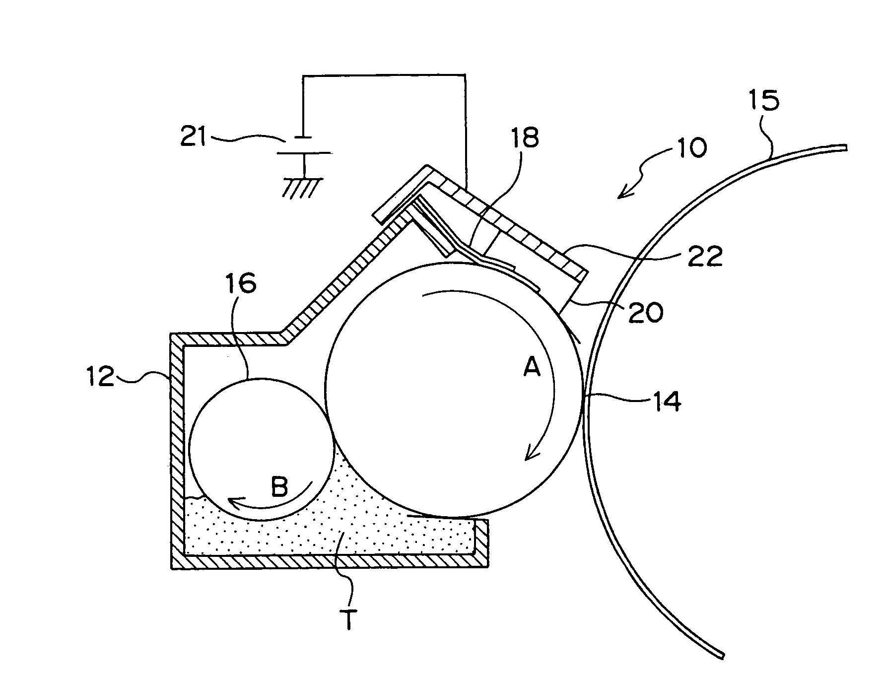
[0043]FIG. 1 is a schematic structural view of a developing device 10 which is an embodiment of the invention. The developing device 10 includes a casing 12 formed of a housing body in which toner T is housed. An opening extending along the longitudinal direction (depth-wise direction of FIG. 1) is formed in the casing 12, and a developing roller 14 is provided at the opening so as to be drivable into rotation along a direction of arrow A. In the developing device 10, the developing roller 14 is placed in opposition and proximity to a drum-like photoconductor 15.

[0044]In the casing 12, a feed roller 16 is disposed in contact with the developing roller 14. As the feed roller 16 is driven into rotation along a direction of arrow B, the toner T is fed to the developing roller 14 so that the a thin toner layer is formed on the outer peripheral surface of the developing roller 14.

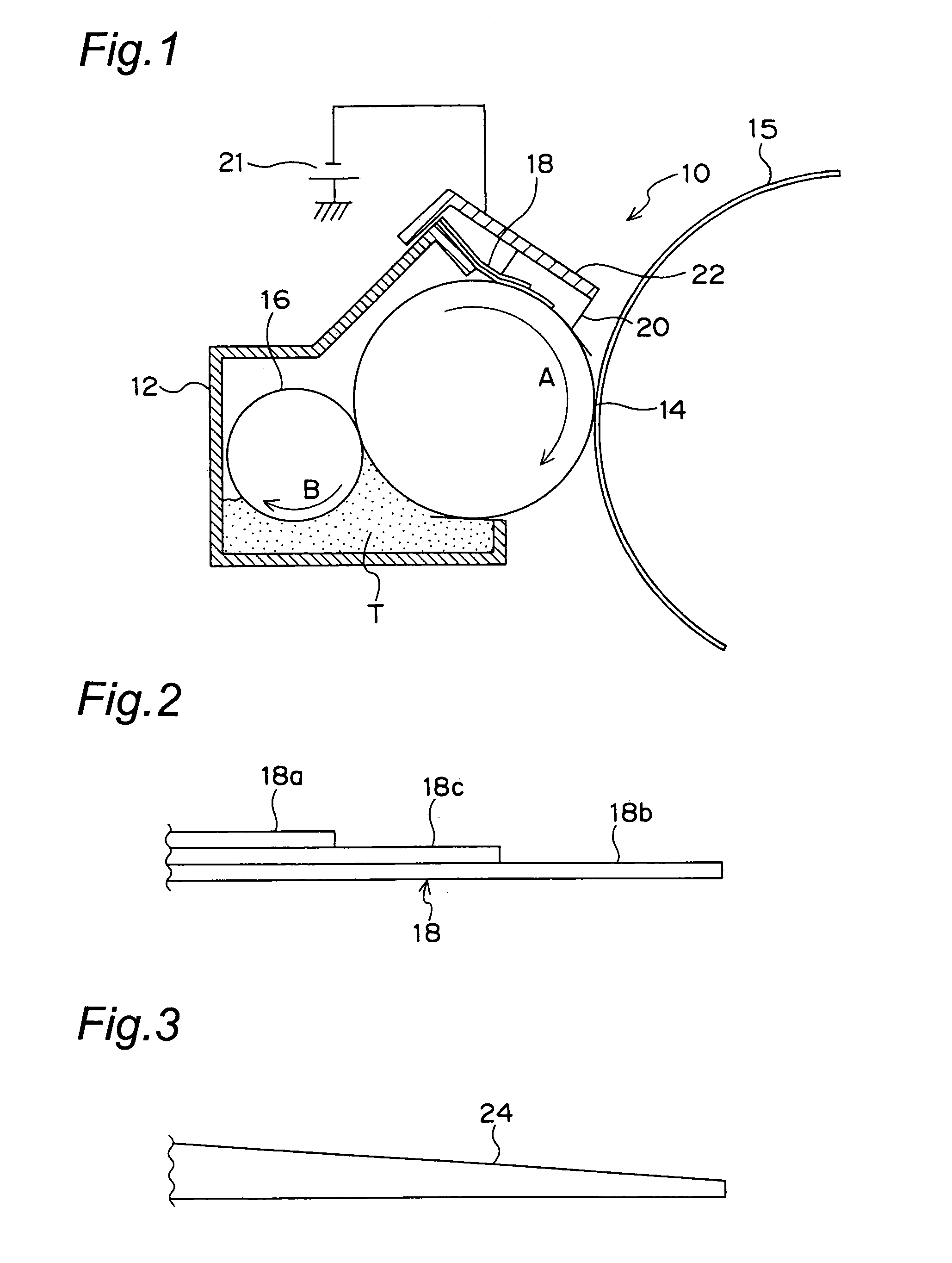
[0045]on top of the casing 12 is fixed a voltage application member 18 formed of, for example, an electricall...


PUM


Abstract

A developing device 10 has a voltage application member 18 which is in contact via a toner layer with a developing roller 14 that rotates while holding the toner layer on its outer peripheral surface. To the toner layer, the voltage application member 18 applies a relatively low voltage in an upstream-side contact portion with respect to a rotational direction of the developing roller 14, and applies a relatively high voltage in a downstream-side contact portion thereof.

Description

RELATED APPLICATION[0001]This application is based on Japanese Patent Application No. 2004-298410, the content of which incorporated herein by reference.BACKGROUND OF THE INVENTION[0002]The present invention relates to a developing device to be used for electrophotographic image formation apparatuses such as printers and copiers.[0003]In electrophotographic image formation apparatuses such as printers and copiers, there has conventionally been used a developing device which develops with toner an electrostatic latent image formed on a surface of a photoconductor to visualize the image. This developing device generally has a developing roller or developing sleeve which rotates while holding charged toner on the outer peripheral surface in a thin layer state, so that toner is fed onto the photoconductor from the developing roller or the like.[0004]Meanwhile, as printers have been wide-spreading in offices rapidly in recent years, users have been becoming increasingly more conscious of...

Claims


Application Information

Patent Timeline
Patent Type & Authority Patents(United States)
IPC IPC(8): G03G15/08
CPCG03G15/065G03G2215/0656
Inventor IMURA, TOMOYUKI
Owner KONICA MINOLTA INC
Why Eureka
Try Eureka