Coordinate measuring machine

a technology of measuring machine and measuring shaft, which is applied in the direction of mechanical measuring arrangement, measurement device, instruments, etc., can solve the problems of small current value and inability to set the appropriate threshold for target speed and acceleration, and achieve the effect of increasing the speed of moving the probe by the movement mechanism and erroneous judgmen

Active Publication Date: 2013-05-14
MITUTOYO CORP
View PDF13 Cites 106 Cited by
  • Summary
  • Abstract
  • Description
  • Claims
  • Application Information

AI Technical Summary

Benefits of technology

[0010]An object of the invention is to provide a coordinate measuring machine that is adapted to set an appropriate threshold for judging a collision between a probe or a movement mechanism and an object, so that an occurrence of the collision between the probe or the movement mechanism and the object can be rapidly judged.
[0012]According to the above aspect of the invention, since the target speed for moving the probe by the movement mechanism is in proportion to the threshold set by the load judging unit, when the target speed for moving the probe by the movement mechanism is small, the load judging unit sets the threshold at a small value; when the target speed is large, the load judging unit sets the threshold at a large value. Accordingly, the coordinate measuring machine can set an appropriate threshold for judging the collision between the probe or the movement mechanism and the object, so that the occurrence of the collision between the probe or the movement mechanism and the object can be rapidly judged.
[0014]The current value detected by the current value detecting unit may exceed the threshold not only when the probe or the movement mechanism and the object collide with each other but also when the speed for moving the probe by the movement mechanism is increased.
[0015]According to the above arrangement, since the load judging unit judges the status of the load applied to the movement mechanism based on the length of the duration in which the current value detected by the current value detecting unit is larger than the threshold, erroneous judgment of the status of the load applied on the movement mechanism can be avoided when the speed for moving the probe by the movement mechanism is increased.

Problems solved by technology

However, when an acceleration of the movement of the probe by the movement mechanism is small (i.e. low speed), the current value is small.
However, since the coordinate measuring machine disclosed in Document 1 sets the threshold in a stepwise manner in accordance with the target speed and the acceleration, an appropriate threshold cannot be set for the target speed and acceleration.

Method used


Image

  • Coordinate measuring machine
  • Coordinate measuring machine
  • Coordinate measuring machine

Examples


Embodiment Construction

)

[0023]An exemplary embodiment of the invention will be described below with reference to the attached drawings.

Arrangement of Coordinate Measuring Machine

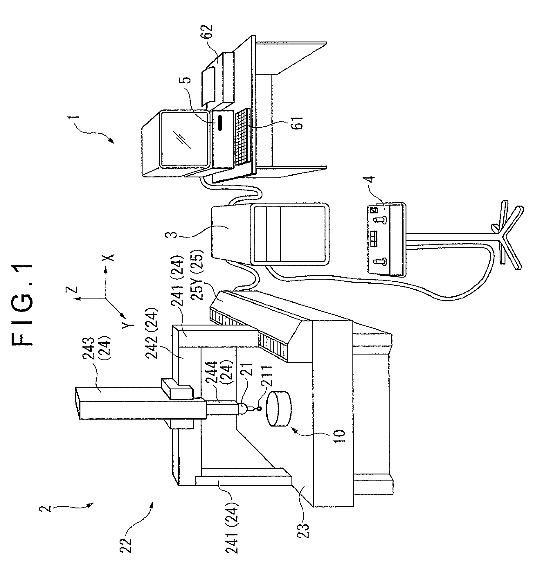
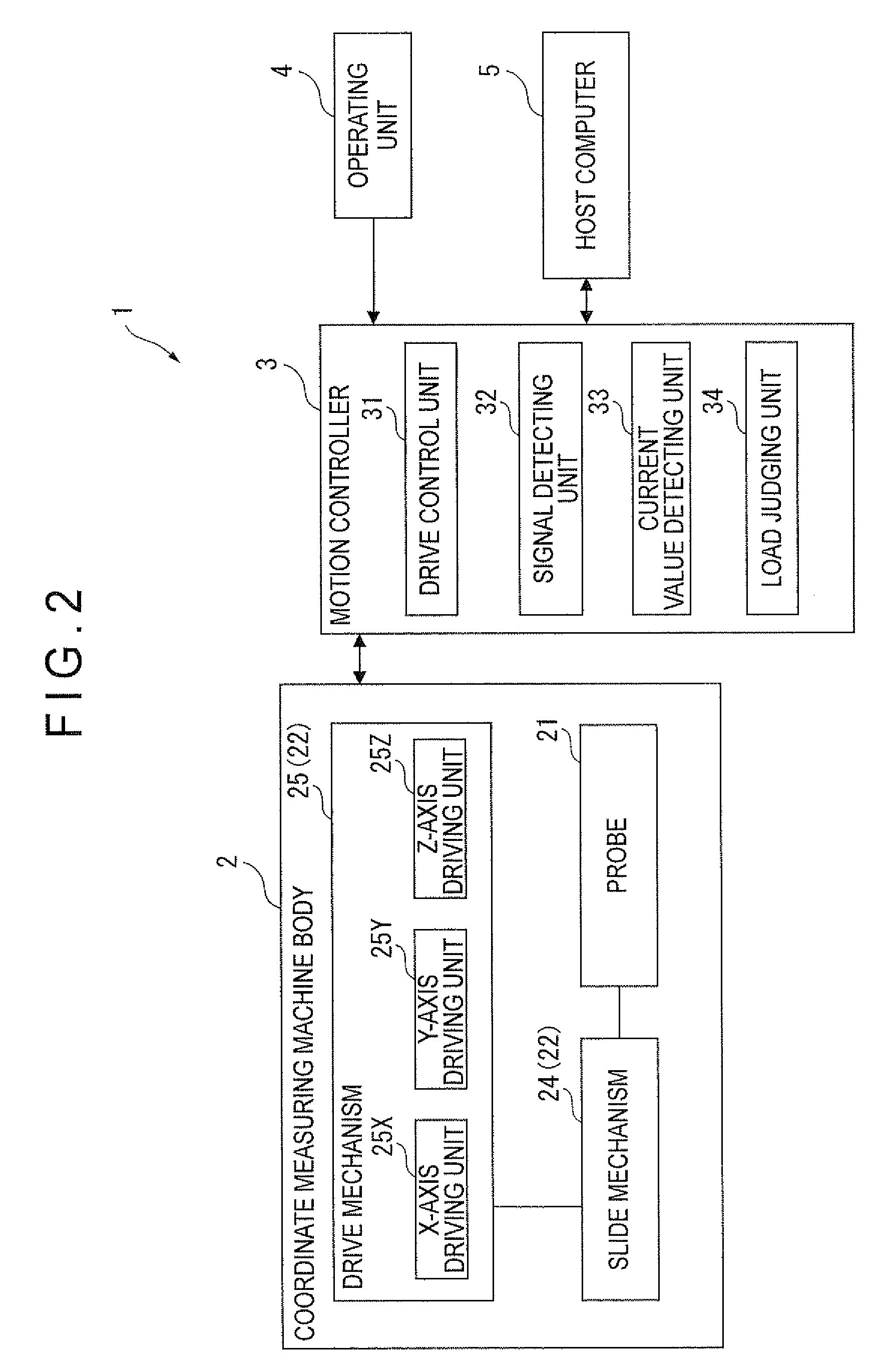
[0024]FIG. 1 is an illustration schematically showing an overall arrangement of a coordinate measuring machine 1 according to an exemplary embodiment of the invention. FIG. 2 is a block diagram schematically showing an arrangement of the coordinate measuring machine 1. Incidentally, an upward direction in FIG. 1 will be denoted as +Z-axis direction, and two axes orthogonal to the Z-axis will be denoted as X-axis and Y-axis.

[0025]As shown in FIG. 1, the coordinate measuring machine 1 includes: a coordinate measuring machine body 2; a motion controller 3 that controls a drive of the coordinate measuring machine body 2; an operating unit 4 that manually operates the coordinate measuring machine body 2 through commands inputted by a control lever and the like; a host computer 5 that issues a predetermined command to the motion control...


PUM


Abstract

A coordinate measuring machine includes: a probe for measuring an object; a movement mechanism for moving the probe; and a motion controller for controlling the movement mechanism. The motion controller includes: a current value detecting unit that detects a current value for moving the probe by the movement mechanism; and a load judging unit that judges a status of a load applied on the movement mechanism based on the current value detected by the current value detecting unit and a threshold that is set in accordance with a target speed for moving the probe by the movement mechanism. The target speed is in proportion to the threshold.

Description

[0001]The entire disclosure of Japanese Patent Application No. 2010-023814 filed Feb. 5, 2010 is expressly incorporated by reference herein.BACKGROUND OF THE INVENTION[0002]1. Field of the Invention[0003]The present invention relates to a coordinate measuring machine.[0004]2. Description of Related Art[0005]A known coordinate measuring machine includes: a probe for measuring an object; a movement mechanism for moving the probe; and a controller for controlling the movement mechanism (see, for instance, Document 1: JP-T-2009-524032). The coordinate measuring machine is designed to stop the movement of the probe when the probe or the movement mechanism and the object collide with each other, for instance, on account of an operation error of a user while the probe is moved by the movement mechanism.[0006]When the probe or the movement mechanism and the object collide with each other, a load applied on the movement mechanism increases, resulting in an increase in a current value for mov...

Claims


Application Information

Patent Timeline
Patent Type & Authority Patents(United States)
IPC IPC(8): G01B5/008
CPCG01B5/008G01B21/047
Inventor USUI, TOMOHIRO
Owner MITUTOYO CORP
Why Eureka
Try Eureka