LED light source with direct AC drive

a technology of led light source and power converter, which is applied in the direction of light source, process and machine control, etc., can solve the problems of reducing the overall efficiency of the light source, limiting the lifetime of the lighting system, and the cost of the power converter is a significant fraction of the cost of a typical led light sour

Active Publication Date: 2013-05-21
BRIDGELUX INC
View PDF7 Cites 3 Cited by
  • Summary
  • Abstract
  • Description
  • Claims
  • Application Information

AI Technical Summary

Problems solved by technology

The cost of the power converter represents a significant fraction of the cost of a typical LED light source.
In addition, the power losses in the power converter reduce the overall efficiency of the light source.
In addition, such AC-DC converters are not as reliable as that of LEDs, and hence, can limit the lifetime of the lighting system.
This simple driving scheme suffers from low efficiency and flicker.
To improve the efficiency, light sources that include a full-wave rectifier have been proposed; however, such light sources still have low efficiency and exhibit flicker.
When the voltage is greater than this turn-on value, the LED will generate light; however, the voltage drop across the LED must also be maintained below a maximum value, Vd, at which the LED will be damaged.
This leads to a 120-cycle flicker.
In addition, the number of LEDs that must be used to generate a predetermined average light intensity is more than three times the number needed in a DC driving scheme, which increases both the component and the packaging costs.
Hence, the flicker problem remains.
Finally, the cost of the light source is increased by the number of switches needed to implement this scheme.

Method used


Image

  • LED light source with direct AC drive
  • LED light source with direct AC drive
  • LED light source with direct AC drive

Examples


Embodiment Construction

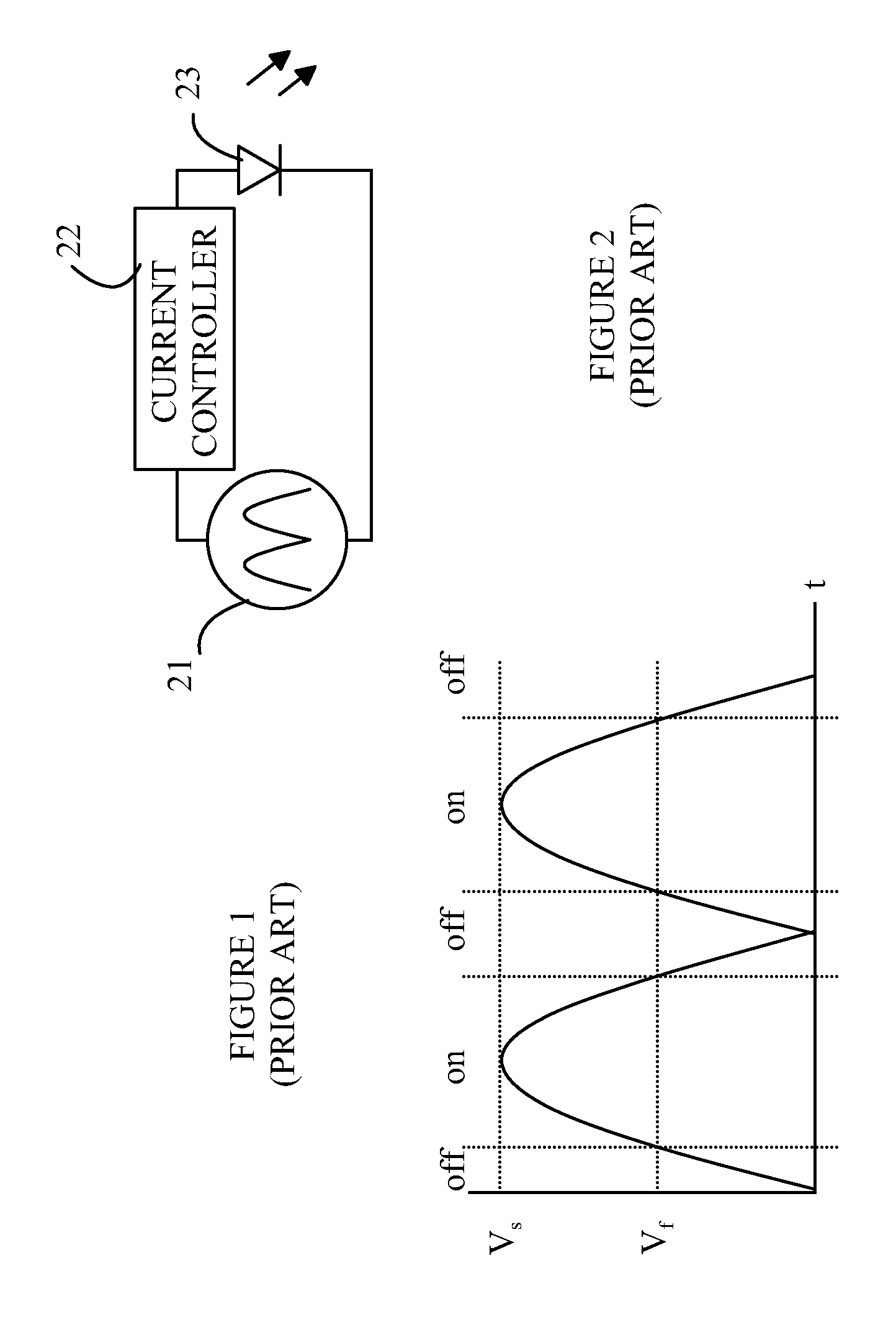
[0020]Normally, LEDs are driven by a constant current source that operates from a DC power supply. As noted above, the cost of the power source represents a significant portion of the overall cost of the light source. To avoid this cost, it has been suggested that LEDs could be operated directly from any AC power source. In such a scheme, a full-wave rectified AC power source is connected directly to the LED. Hence, the LED is driven by a power source that is no longer a constant current source. Since the current through an LED is an exponential function of the driving voltage at voltages above the minimum voltage, Vf, at which the LED will be turned on, care must be taken to make sure that the voltage does not reach a point at which the current through the LED will cause damage to the LED. In addition, it is useful to maintain the current below that at which the efficiency of the LED is reduced and too much heat is generated.

[0021]Referring now to FIG. 1, which illustrates an LED 2...


PUM


Abstract

A light source and method for operating a light source are disclosed. The present invention includes a light source and method for using the same. The light source includes a power coupler, a reconfigurable two-dimensional LED array and a controller. The power coupler is configured to receive a power potential that varies as a function of time. The LED array has a plurality of configurations of LEDs, each configuration being characterized by a minimum bias potential and a maximum bias potential. The LED array generates light when a potential between first and second power terminals is greater than the minimum bias potential. The controller varies the configuration of the array such that the power potential remains between the minimum and maximum bias potentials as the power potential varies.

Description

BACKGROUND OF THE INVENTION[0001]Light-emitting diodes (LEDs) are an important class of solid-state devices that convert electric energy to light Improvements in these devices have resulted in their use in light fixtures designed to replace conventional incandescent and fluorescent light sources. The LEDs have significantly longer lifetimes and, in some cases, significantly higher efficiency for converting electric energy to light.[0002]The conversion efficiency of individual LEDs is an important factor in addressing the cost of high power LED light sources. The conversion efficiency of an LED is defined to be the electrical power dissipated per unit of light that is emitted by the LED. Electrical power that is not converted to light in the LED is converted to heat that raises the temperature of the LED. The light conversion efficiency of an LED decreases with increasing current through the LED.[0003]LEDs are typically powered from a DC power source or a modulated square wave source...

Claims


Application Information

Patent Timeline
Patent Type & Authority Patents(United States)
IPC IPC(8): G05F1/00H05B39/04
CPCH05B33/0824H05B45/44
Inventor YANG, LONG
Owner BRIDGELUX INC
Why Eureka
Try Eureka