Turn-on bus transmitter with controlled slew rate
A driver, amplifier technology, applied in the direction of reliability improvement modification, pulse technology, electronic switch, etc., can solve the problem of long on-delay, impossible to obtain bus level, pull down bus voltage, etc.
- Summary
- Abstract
- Description
- Claims
- Application Information
AI Technical Summary
Problems solved by technology
Method used
Image
Examples
Embodiment Construction
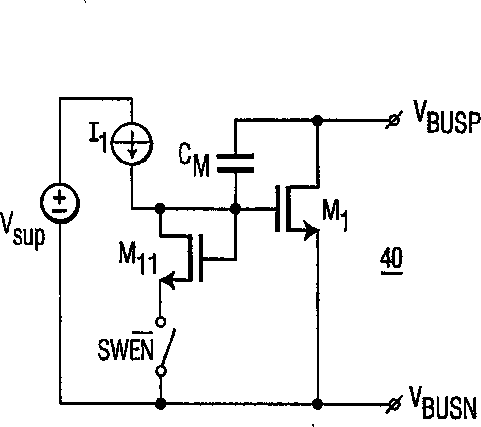
[0027] Figure 4 An example of a driver / amplifier 40 with a controllable slew rate with fast on-time is shown. In this circuit 40, current I1 always flows into the M1 gate node. When output stage operation is disabled by closing switch SWEN, current I1 flows in diode-connected transistor M11. The combination of transistor M11 and output stage M1 now operates as a current mirror and pre-biases the output stage at a drain current determined by I1 and the ratio of width to length (W / L) of M1, M11. As a result, the gate-source voltage of M1 is pre-biased at a voltage level greater than its threshold voltage. When the output stage is turned on by opening switch SWEN, the gate-to-source voltage of M1 only needs to increase by a small amount to fully turn on, thereby achieving a fast turn-on time.
[0028] Figure 5 An example of a driver / amplifier 50 with fast on-time and controllable slew rate with controllable output voltage level is shown. This is accomplished by a controllab...
PUM
 Abstract
Description
Claims
Application Information
 - R&D
- Intellectual Property
- Life Sciences
- Materials
- Tech Scout
- Unparalleled Data Quality
- Higher Quality Content
- 60% Fewer Hallucinations
Browse by: Latest US Patents, China's latest patents, Technical Efficacy Thesaurus, Application Domain, Technology Topic, Popular Technical Reports.
© 2025 PatSnap. All rights reserved.Legal|Privacy policy|Modern Slavery Act Transparency Statement|Sitemap|About US| Contact US: help@patsnap.com


