Protective cover for communication device

a technology for communication devices and protective covers, applied in the field of protective covers, can solve the problems of not being protected from sand or dirt particles, cell phones and other mobile devices are not waterproo

Inactive Publication Date: 2013-06-04
MORE CHARM
View PDF38 Cites 100 Cited by
  • Summary
  • Abstract
  • Description
  • Claims
  • Application Information

AI Technical Summary

Benefits of technology

[0012]A latch in the form of a protuberance is formed in and projects from a preselected wall of the cover. An opening is formed in the lock housing and faces the cover when the cover is unlocked. The opening has a width and depth sufficient to fully receive the protuberance when the cover is closed. A one hundred eighty degree (180°) rotation of the lock housing in a first direction positions the opening on an opposite side of the container 10, capturing the protuberance and thus causing the cover to tightly engage base, compressing the bead of the plastic sheet.
[0013]A one hundred eighty degree (180°) rotation of the lock housing in a second direction opposite to the first direction releases the protuberance and frees the cover from the base.
[0015]The primary object of the invention is to protect mobile devices from water or airborne particulates that might damage the device.

Problems solved by technology

Cell phones and other mobile devices are not waterproof.
Moreover, they are not protected from sand or dirt particles that may be present in an outdoor environment.
Many people enjoy water-related and other outdoor sports and other activities, however, and their mobile devices may be dropped into water, subjected to sand particles, rain, and the like.

Method used


Image

  • Protective cover for communication device
  • Protective cover for communication device
  • Protective cover for communication device

Examples


first embodiment

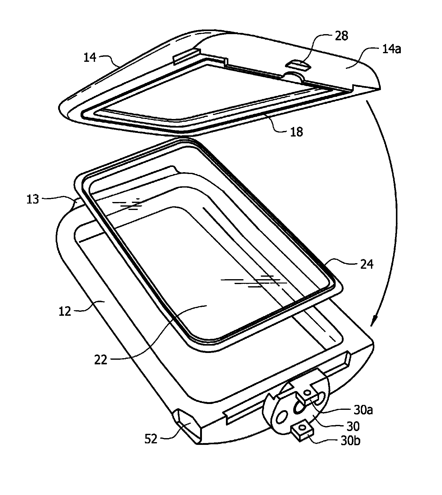
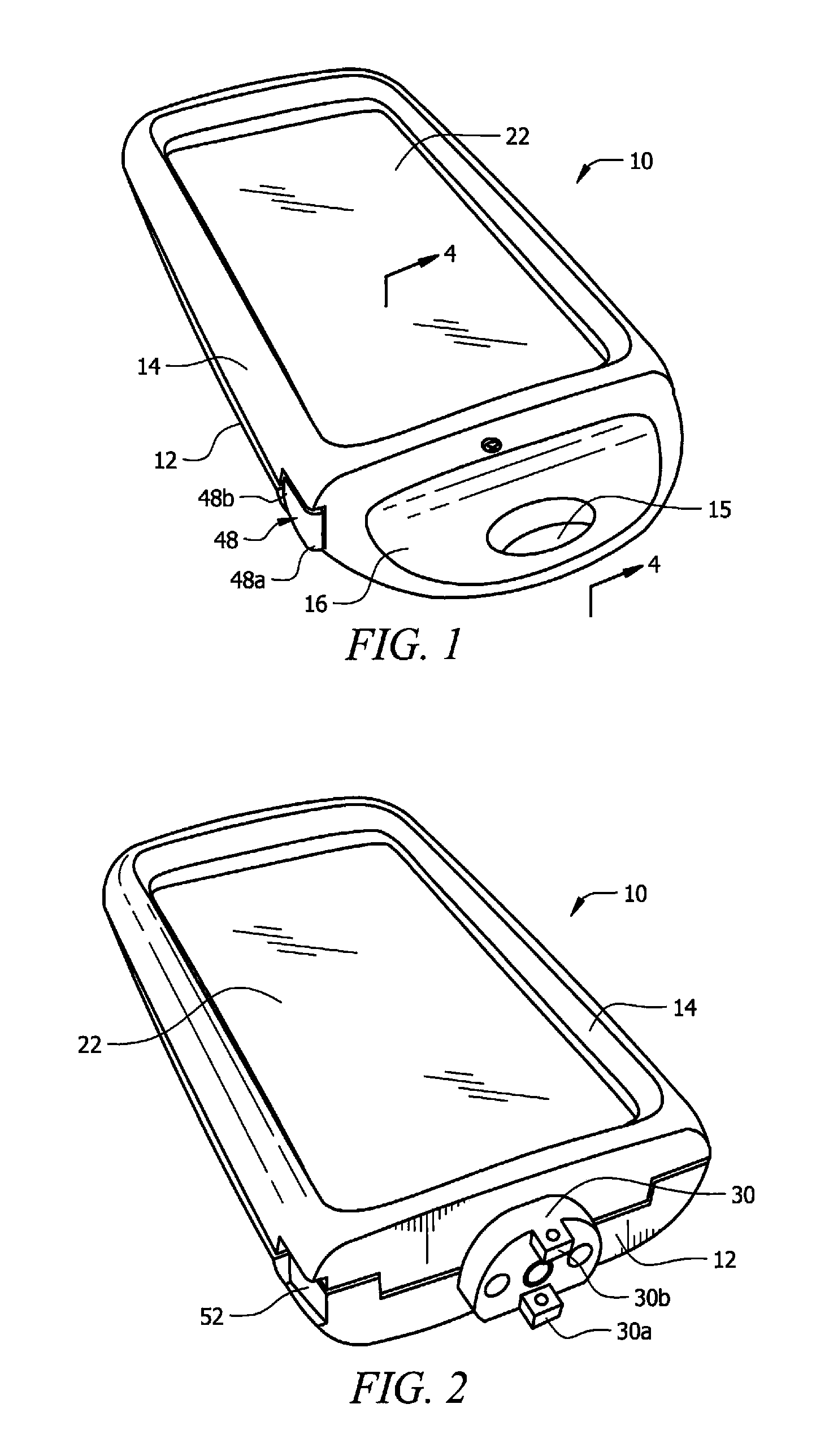
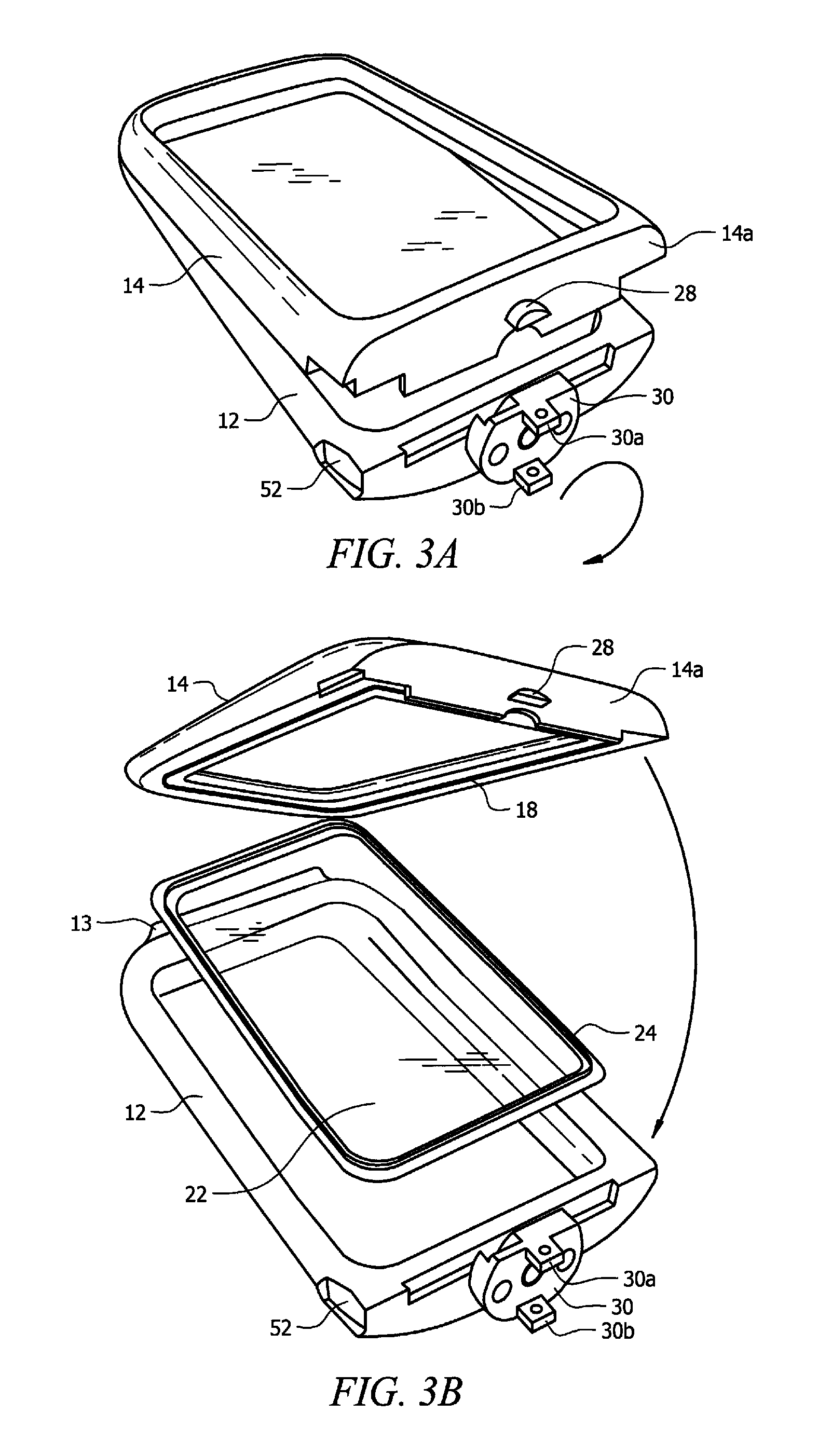
[0038]In a first embodiment, protective container 10 includes a container base 12, a cover 14, a hinge 13 (FIG. 3B) for hingedly interconnecting the base and cover to one another, and a lock handle 16 for locking cover 14 to base 12.

[0039]Groove 18 circumscribes interior wall 20 of cover 14. A thin, transparent sheet of plastic 22 has bead 24 formed in its periphery and bead 24 is press fit into said groove so that said thin, transparent sheet of plastic closely overlies the operative face of a mobile device when cover 14 is locked to base 12.

[0040]Lock handle 16 is substantially hollow and is pivotally mounted about pivot pin 26 having boss 26a. More particularly, pivot pin 26 extends from transverse leading wall 12a of base 12 and engages central bore 31 of lock insert 30 (FIG. 5B) so that lock handle 16 rotates about pivot pin 26 when manually manipulated as more fully disclosed below.

[0041]Protuberance 28 (FIGS. 3A and 3B) projects from transverse leading wall 14a of cover 14. O...

second embodiment

[0052]In a second embodiment, depicted in FIGS. 7 and 8, protective container 60 includes a container base 62, a cover 64, a hinge 66 for hingedly interconnecting base 62 and cover 64 to one another, and a plurality of quick-release latches 68, 70, and 72 for releasably latching cover 64 to base 62. These latches are known as over-center latches in the industry. They require a catch formed on a first part of the two (2) parts to be latched together and a double-axle latch on a second part of said two (2) parts. More particularly, as depicted in FIG. 8, catches 68a, 70a, and 72a are associated with latches 68, 70, and 72, respectively.

[0053]Groove 76 circumscribes interior wall 78 of cover 64. A thin, transparent sheet of plastic 80 has bead 82 formed in its periphery and bead 82 is press fit into groove 76 so that said thin, transparent sheet of plastic closely overlies the operative face of a mobile device when cover 64 is locked to base 62.

[0054]In the first and second embodiments...


PUM

PropertyMeasurementUnit
rotationaaaaaaaaaa
transparentaaaaaaaaaa
widthaaaaaaaaaa

Abstract

A water-proof container for holding a mobile device includes a base adapted to support a mobile device, a cover, a hinge for interconnecting the base and cover to one another, and a locking mechanism for locking the cover to the base. A groove is formed in an interior wall of the cover in circumscribing relation to the cover. A thin, transparent sheet of plastic has a bead formed in its peripheral edge and the bead is press fit into the groove so that the thin sheet of plastic closely overlies the operative face of the mobile device when the cover is latched to the base. A hollow lock housing is pivotally mounted about a pivot pin. A one hundred eighty degree (180°) rotation of the lock housing positions the opening on an opposite side of the container 10, capturing the latch.

Description

CROSS-REFERENCE TO RELATED APPLICATIONS[0001]This application claims priority to currently U.S. provisional patent application No. 61 / 390,351, entitled “Protective Container for Communication Device,” filed by the same inventor on Oct. 6, 2010, is a continuation-in-part application and claims priority to non-provisional application No. 13 / 018,929, filed by the same inventor on Feb. 1, 2011, entitled “Protective Container for Communication Device” which claims priority to currently U.S. provisional patent application No. 61 / 358,198, entitled “Protective Container for Communication Device,” filed by the same inventor on Jun. 24, 2010, the contents of which are hereby incorporated by reference.BACKGROUND OF THE INVENTION[0002]1. Field of the Invention[0003]This invention relates, generally, to protective containers. More particularly, it relates to a buoyant container that prevents cell phones and similar electronic mobile deices from sinking in water.[0004]2. Description of the Prior ...

Claims


Application Information

Patent Timeline
Patent Type & Authority Patents(United States)
IPC IPC(8): B65D85/00
CPCA45C11/00A45C11/22A45C2011/002Y10T292/426Y10T292/385
Inventor SO, KAR MING
Owner MORE CHARM
Why Eureka
Try Eureka