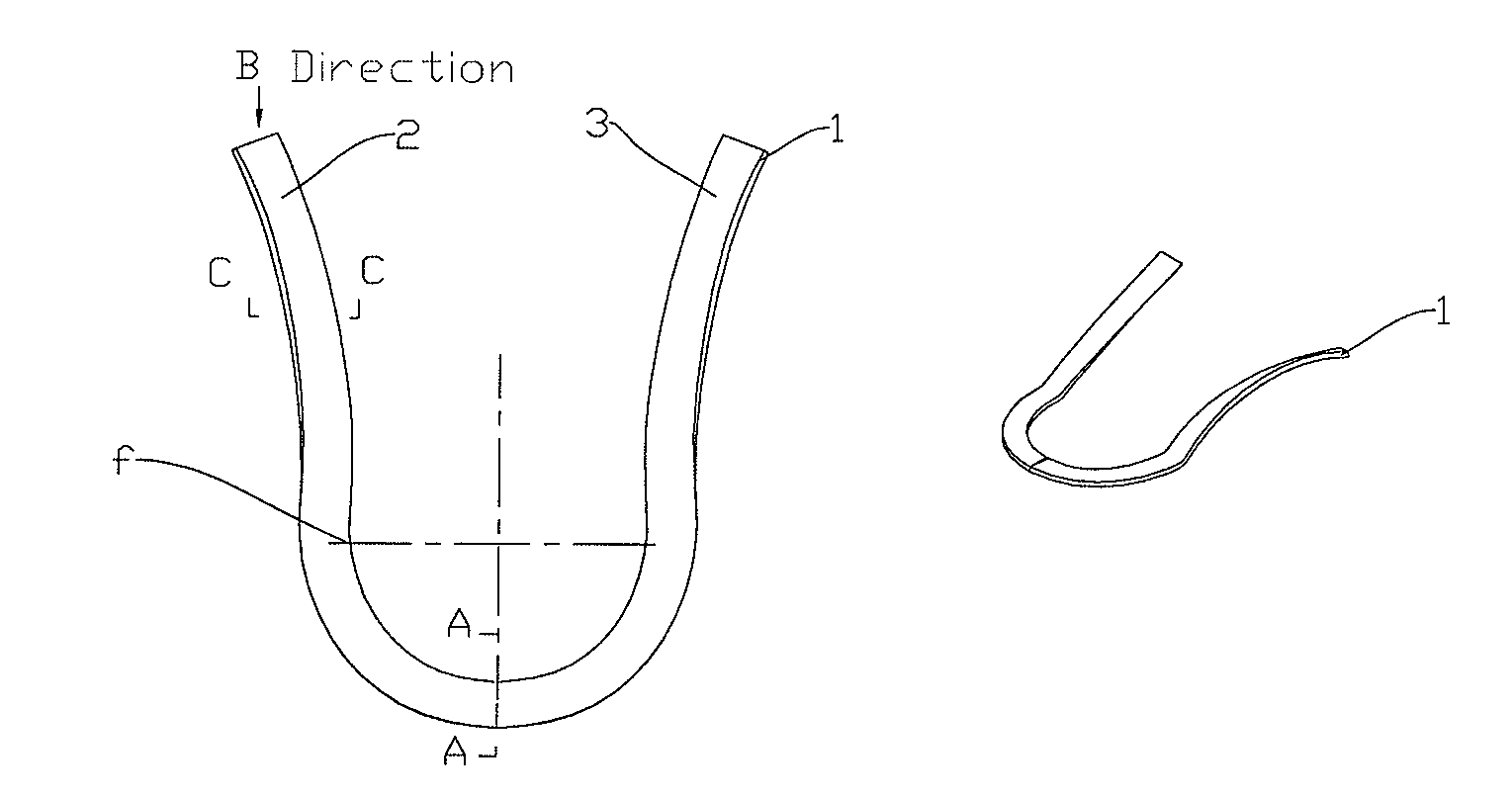
Three-dimensional heart position support frame for low-heart underwear
a support frame and low-heart technology, applied in the direction of brassieres, apparel, applications, etc., can solve the problems of not only limiting the heart position, but also unable to coordinate the cleavage line of outerwear very well, and achieve excellent bracing effect and simple structure.
- Summary
- Abstract
- Description
- Claims
- Application Information
AI Technical Summary
Benefits of technology
Problems solved by technology
Method used
Image
Examples
first embodiment
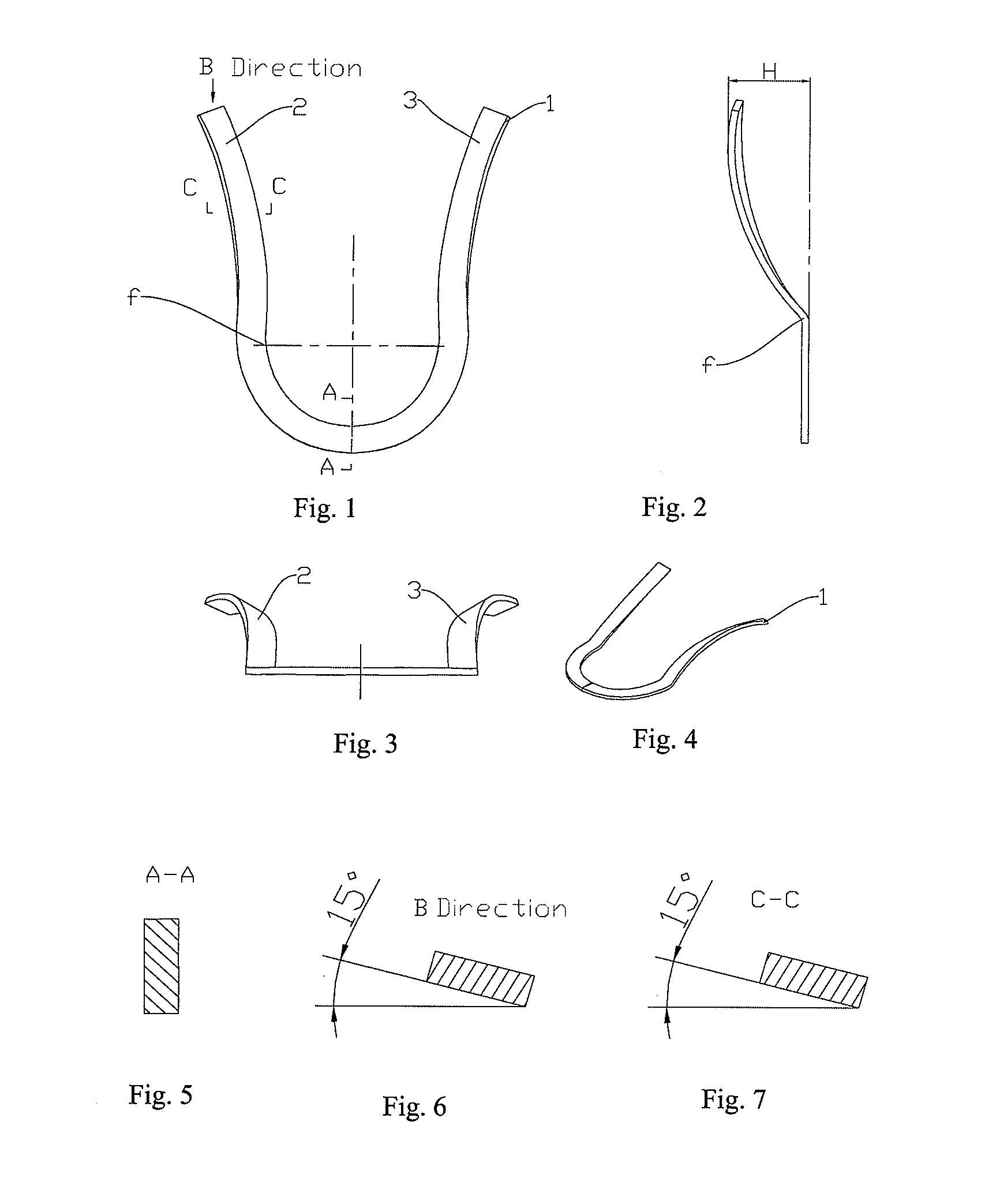
[0040]The first embodiment is shown in FIGS. 1, 2, 3, 4, 5, 6 and 7.
[0041]For achieving the objective of the invention, a body of the support frame 1 is a U-shaped support frame, and blank structure of the body of the support frame 1 is a flat wire; the body of the support frame is a U-shaped support frame, and blank structure of the body of the support frame is a flat wire; wire surfaces 2, 3 of two vertical portions of the body of the support frame are correspondingly twisted outwardly at an angle with respect to a vertical axis, forming an anticlockwise angle of 15°-85° with a vertical plane. The twist starts from a position of the maximum radius f of semicircular lower portion of the U shape. The wire surfaces 2, 3 of the two vertical portions are of an arc-shaped structure which is curved outwardly, the outwardly curved portion with a maximum curvature being offset in a distance of 5 mm-50 mm with respect to midpoint of the bottom portion of the U-shaped support frame. In this ...
second embodiment
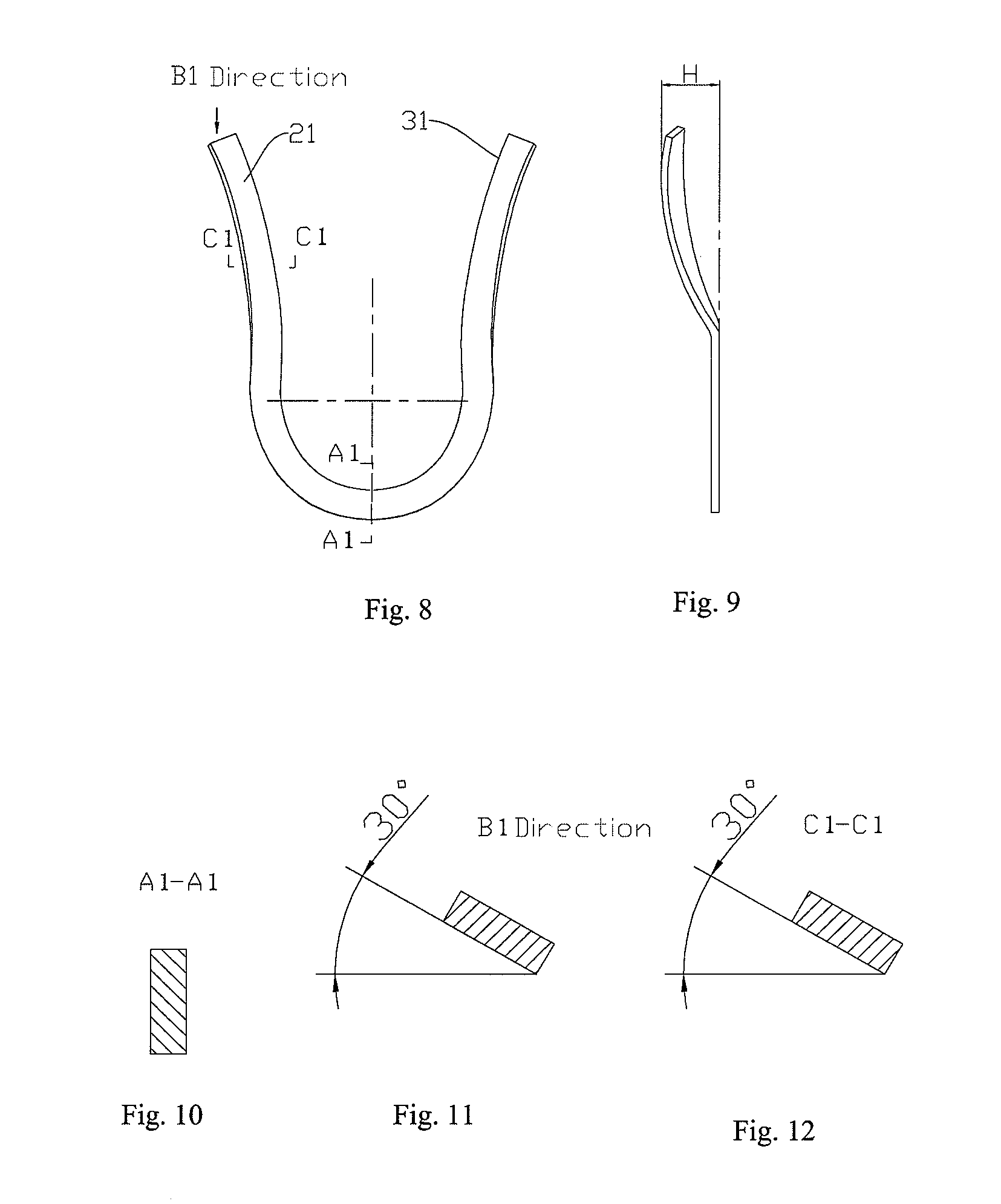
[0045]The second embodiment is shown in FIGS. 8, 9, 10, 11 and 12.
[0046]In this embodiment, wire surfaces 21, 31 of two vertical portions of the body of the support frame are corresponding twisted outwardly at an angle with respect to a vertical axis, forming an anticlockwise angle of 30° with respect to a vertical plane. The twist starts from a position of the maximum radius of semicircular lower portion of the U shape. The wire surfaces 21, 31 of the two vertical portions are of an arc-shaped structure which is curved outwardly, the outwardly curved portion with a maximum curvature being offset in a distance H of 20 mm with respect to midpoint of the bottom portion of the U-shaped support frame. As can be seen from FIGS. 10, 11 and 12, a plane of the wide flat wire is vertical in the A1-A1 sectional view. With regard to the wires surface of its vertical portions, as seen in the B1 direction, the end surface of the wire surface 2 is at an angle of 30° with respect to the vertical p...
third embodiment
[0049]The third embodiment is shown in FIGS. 13, 14, 15, 16 and 17.
[0050]Wire surfaces 22, 32 of two vertical portions of the body of the support frame are correspondingly twisted outwardly at an angle with respect to a vertical axis, forming an anticlockwise angle of 60° with respect to a vertical plane. The twist starts from a position of the maximum radius of semicircular lower portion of the U shape. The wire surfaces 22, 32 of the two vertical portions are of an arc-shaped structure which is curved outwardly, the outwardly curved portion with a maximum curvature being offset in a distance H of 40 mm with respect to midpoint of the bottom portion of the U-shaped support frame. As can be seen from FIGS. 15, 16 and 17, a plane of the wide flat wire is vertical in the A2-A2 sectional view. With regard to the wires surface of its vertical portions, as seen in the B2 direction, the end surface of the wire surface 22 is at an angle of 60° with respect to the vertical plane. Moreover, ...
PUM
 Abstract
Description
Claims
Application Information
 - R&D
- Intellectual Property
- Life Sciences
- Materials
- Tech Scout
- Unparalleled Data Quality
- Higher Quality Content
- 60% Fewer Hallucinations
Browse by: Latest US Patents, China's latest patents, Technical Efficacy Thesaurus, Application Domain, Technology Topic, Popular Technical Reports.
© 2025 PatSnap. All rights reserved.Legal|Privacy policy|Modern Slavery Act Transparency Statement|Sitemap|About US| Contact US: help@patsnap.com


