Surgical base unit and retractor support mechanism

a technology of retractor and base unit, which is applied in the field of surgical base unit and retractor support mechanism, can solve the problems of unwieldy method of mounting retractor b>28/b> and is subject to potential sterility breach

Active Publication Date: 2013-06-11
STERN LESLIE
View PDF26 Cites 51 Cited by
  • Summary
  • Abstract
  • Description
  • Claims
  • Application Information

AI Technical Summary

Problems solved by technology

This method of mounting retractor 28 is unwieldy and subject to a potential breach of sterility while accessing the surgical site.

Method used


Image

  • Surgical base unit and retractor support mechanism
  • Surgical base unit and retractor support mechanism
  • Surgical base unit and retractor support mechanism

Examples


Embodiment Construction

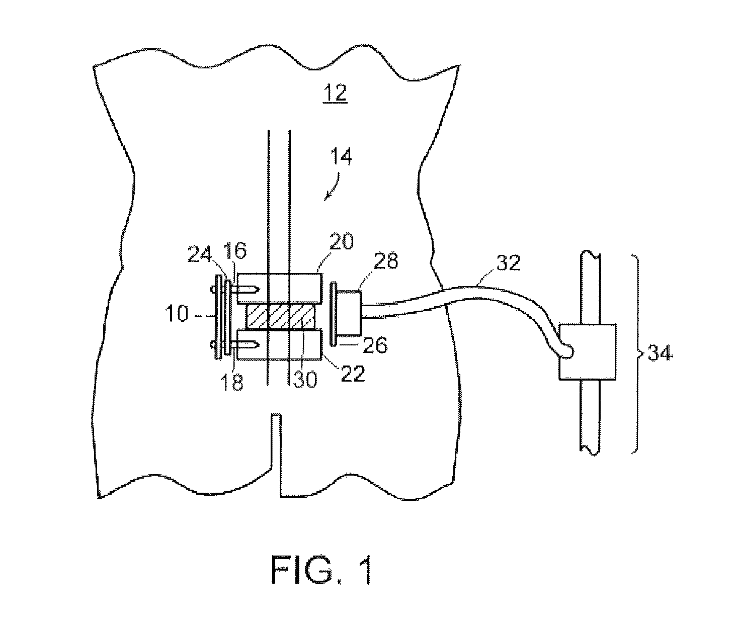
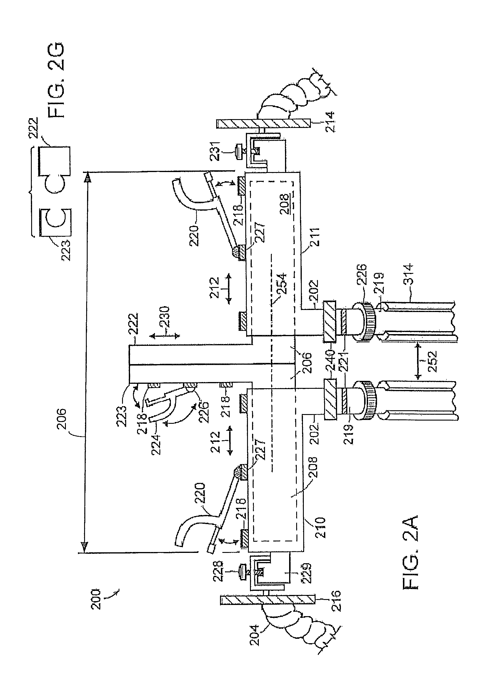
[0027]In accordance with preferred embodiments of the present invention, forces may be applied to a bone with respect to an effectively fixed fulcrum, or between adjacent bones, by a trestle-structure base unit designated generally by numeral 200, as now described with reference to FIG. 2A. Base unit 200 may function alone, or in conjunction with a retractor 500 (shown in FIG. 5) supported by the base unit. The purpose of retractor 500, namely, for holding the edge of a surgical incision, has been discussed above.

[0028]Base unit 200 has two legs (or “posts”) 202, each of which is coupled, as described in further detail below, to a pedicle screw 16, 18, anchored to the skeletal system of the patient. Trestle base unit 200 may also serve to support one or more flexible arms 204 to which, in turn, the retractor 500 of FIG. 5 is coupled. Leg extensions 219 are coupled to legs 202, typically via rotating coupling 240, as further discussed, below, with reference to FIG. 2B. It should be n...


PUM


Abstract

An apparatus and methods for exerting force on a first bone with respect to a fulcrum, which may be a second bone. A base structure, mechanically coupled to the fulcrum, is coupled to the closure top so that a force may be exerted by the base structure, acting against the fulcrum, in at least one of axial and transverse directions with respect to a pedicle screw inserted into bone. A leg extension, allowing force to be applied through the pedicle screw to a bone, has a first end rotatably coupled to the base structure; and a second end threaded as the closure top. The base structure may also support a retractor in a manner local to the immediate region of surgery.

Description

[0001]The present application is a continuation-in-part application of U.S. Ser. No. 11 / 098,770, filed Apr. 4, 2005 and issued as U.S. Pat. No. 7,637,914, and, like that application, claims priority from U.S. Provisional Application Ser. No. 60 / 598,739, filed Aug. 4, 2004. Both of the foregoing patent applications are incorporated herein by reference.TECHNICAL FIELD[0002]The present invention pertains to devices and methods for locally securing a support base at the site of an incision by anchoring to a pedicle screw inserted into one or more bones, which support base may be used for exerting relative forces on the bones as well as for supporting a further surgical retractor.BACKGROUND ART[0003]Fusion of lumbar vertebrae is performed under circumstances including those in which degenerative disk disease, scoliosis, or other deformity indicates that stopping motion between adjacent vertebral segments is desirable. The fusion procedure entails inserting a bone graft between vertebral ...

Claims


Application Information

Patent Timeline
Patent Type & Authority Patents(United States)
IPC IPC(8): A61B17/70
CPCA61B17/025A61B17/7077A61B2017/0256A61B2019/307A61B2090/037
Inventor STERN, LESLIE
Owner STERN LESLIE
Why Eureka
Try Eureka