Electric connector and electric connector assembly

a technology of electric connectors and assembly parts, which is applied in the direction of coupling device connection, coupling protective earth/shielding arrangement, coupling/disengagement of coupling parts, etc., can solve the problems of increasing the possibility of electromagnetic noise emission from the connecting portion to the outside, and affecting productivity. , to achieve the effect of excellent electromagnetic shielding function, simple structure and low cos

Active Publication Date: 2013-06-18
DAIICHI SEIKO CO LTD
View PDF13 Cites 15 Cited by
  • Summary
  • Abstract
  • Description
  • Claims
  • Application Information

AI Technical Summary

Benefits of technology

[0009]Thus, an object of the present invention is to provide an electric connector and electric connector assembly allowing electromagnetic shielding regarding a connecting portion with a main wiring board to be excellently achieved with a simple structure without impairing productivity.
[0010]Also, another object of the present invention is to provide an electric connector and electric connector assembly allowing adherence of foreign substances, such as a solder material, to a contact portion of conductive contacts to be excellently prevented with a simple structure.
[0016]According to the present invention with the above-described structure, with the fit-in holding member being rotated to the fit-in acting position before fitting in the counterpart connector, the contact portion of the conductive contacts to be connected to the counterpart connector is covered with the conductive cover part for protection. Therefore, adherence of foreign substances, such as a solder material, to the contact portion can be prevented, thereby ensuring excellent electrical connection.
[0019]According to the present invention with the above-described structure, the entire connector is covered with the conductive cover part. Therefore, an excellent electromagnetic shielding function can be achieved, and the stiffness of the fit-in holding member can be increased by the extended conductive cover part.
[0020]As described above, in the present invention, the fit-in holding member being rotated from the fit-in releasing position to the fit-in acting position to maintain a connector fit-in state is provided with the conductive cover part covering the connecting portion between the counterpart connector and the main wiring board when the fit-in holding member is rotated to the fit-in acting position in the state of fitting in the counterpart connector. When both of the connectors fit in together, the connecting potion between the conductive contacts and the main wiring board is covered to immediately cause electromagnetic shielding of that connecting portion, thereby eliminating an increase in the number of manufacturing processes. Also, the connection state at the connecting portion with the main wiring board can be clearly confirmed until the fit-in holding member is rotated to the fit-in acting position. Therefore, electromagnetic shielding regarding the connecting portion with the main wiring board can be excellently achieved with a simple structure without impairing productivity, and reliability of the electric connector can be significantly increased at low cost.
[0021]Also, in the present invention, the fit-in holding member being rotated from the fit-in releasing position to the fit-in acting position to maintain a connector fit-in state is provided with the conductive cover part covering the contact portion of the conductive contacts when the fit-in holding member is rotated to the fit-in acting position when not fitting in the counterpart connector. With the fit-in holding member being rotated to the fit-in acting position before fitting in the counterpart connector, the contact portion of the conductive contacts to be connected to the counterpart connecter is covered with the conductive cover part for protection. Therefore, adherence of foreign substances, such as a solder material, to the contact portion can be prevented, thereby ensuring excellent electrical connection. Thus, adherence of foreign substances, such as a solder material, to the contact portion of the conductive contacts can be excellently prevented with a simple structure, and reliability of the electric connector can be significantly increased at low cost.

Problems solved by technology

Therefore, with an increase in frequency of the transmission signal particularly in recent years, the influence of external electromagnetic noise on the connecting portion with the main wiring board has been becoming impossible to ignore, and the possibility of emission of electromagnetic noise from the connecting portion to the outside has been increasing.
When the conductive tape is used, however, a relatively bothersome working process of affixing the conductive tape is added, and therefore productivity tends to decrease.
Moreover, when the conductive shell is extended for coverage, the connecting portion between the conductive contacts and the main wiring board cannot be checked by a visual inspection, an image inspection, or the like, thereby disadvantageously making it difficult to conduct an inspection and a check to see whether the connection works without any trouble.
At the time of solder connection between the conductive shell and the ground bar, a flux contained in a solder material is abruptly blown due to heating of the solder material, and therefore the solder material and the flux scatter to be adhered to a portion other than the originally-intended connecting portion, for example, a contact portion of the conductive contacts, thereby possibly causing an electrical problem.

Method used


Image

  • Electric connector and electric connector assembly
  • Electric connector and electric connector assembly
  • Electric connector and electric connector assembly

Examples


Embodiment Construction

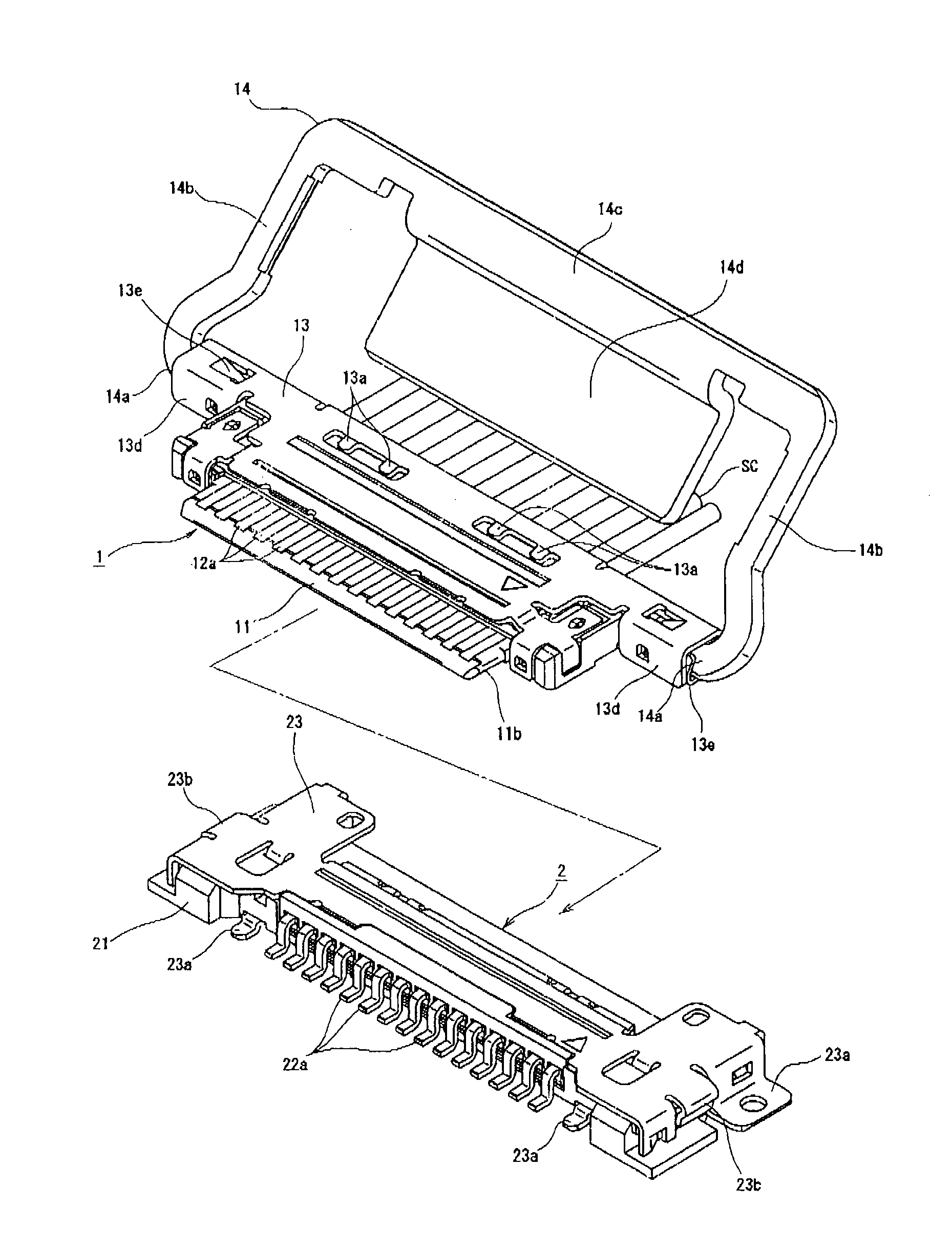
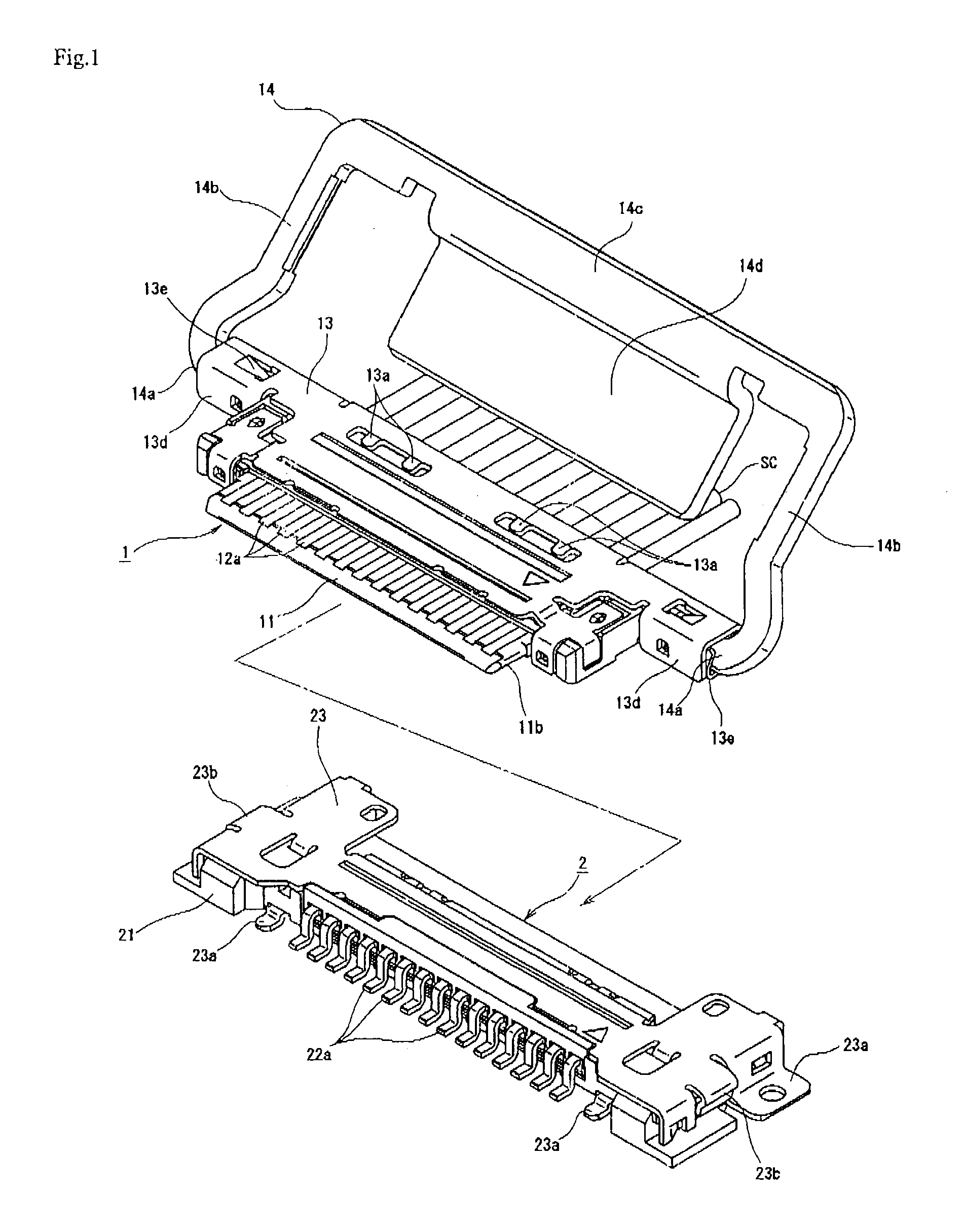
[0032]Embodiments when the present invention is applied to an electric connector for connecting a plurality of coaxial cables to a printed wiring board side are described in detail below based on the drawings.

[Summary of Entire Structure of Electric Connector Assembly]

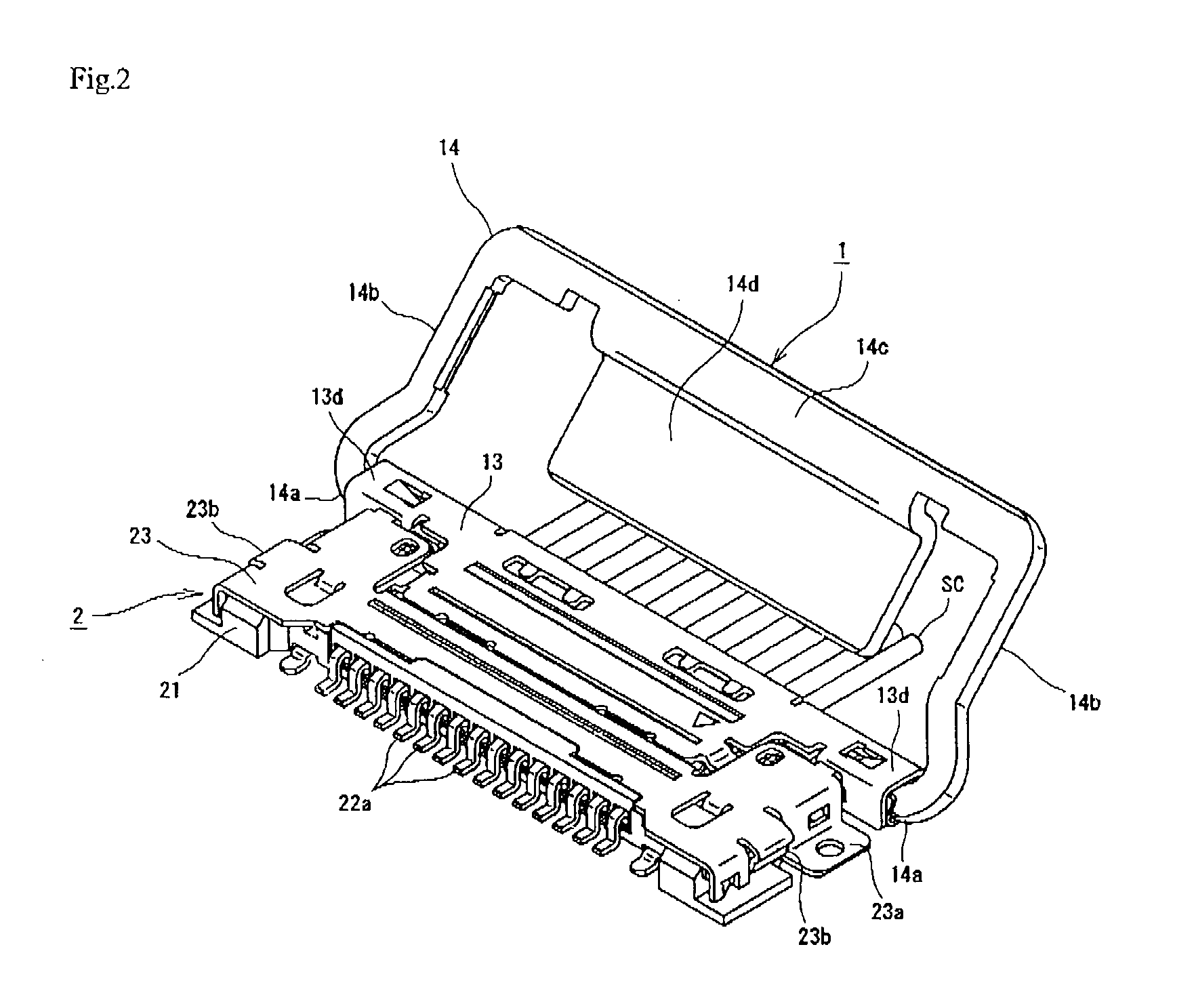
[0033]First, an electric connector assembly according to a first embodiment of the present invention depicted in FIGS. 1 to 7 configures a horizontal fit-in type electric connector including a plug connector 1 to which a terminal portion of coaxial cables SC are coupled and a receptacle connector 2 mounted on a main printed wiring board B. The plug connector 1 as a first connector is arranged so as to face the receptacle connector 2 as a second connector, which is a fit-in counterpart, in an approximately horizontal direction. From this state, with the plug connector 1 is moved so as to come close along the surface of the main printed wiring board B, as depicted in FIG. 7, a tip projection part of the plug connector 1 ...


PUM


Abstract

To allow electromagnetic shielding regarding a connecting portion between conductive contacts and a main wiring board to be excellently achieved with a simple structure without impairing productivity, a fit-in holding member being rotated from a fit-in releasing position to a fit-in acting position to maintain a state where connectors fit in together by rotation is provided with a conductive cover part covering a connecting portion between a counterpart connector and the main wiring board when the fit-in holding member is rotated to the fit-in acting position, and the connecting portion is covered with the conductive cover part. Electromagnetic shielding of that portion is performed simultaneously with the time when both of the connectors fit in together, thereby eliminating an increase in the number of manufacturing processes. Also, the connection state at the connecting portion between a conductive contact and and the main wiring board can be clearly confirmed until the fit-in holding member is rotated to the fit-in acting position.

Description

BACKGROUND OF THE INVENTION[0001]1. Field of the Invention[0002]The present invention relates to an electric connector and electric connector assembly with a fit-in structure for electrically connecting any appropriate signal transmission medium to a main wiring board.[0003]2. Description of the Related Art[0004]In general, in various electric devices and others, an electric connector is widely used for connecting a terminal part of a signal transmission medium formed of a flexible printed circuit (FPC), a flexible flat cable (FFC), a coaxial cable, or others to a main printed wiring board. The electric connector is configured in a manner such that, to a first connector (a receptacle connector) mounted on a main printed wiring board, a second connector (a plug connector) to which a signal transmission medium such as a coaxial cable is inserted and both of the connectors fit in together. Signal transmission is performed though conductive contacts (conductive terminals) arranged in a ...

Claims


Application Information

Patent Timeline
Patent Type & Authority Patents(United States)
IPC IPC(8): H01R13/648
CPCH01R12/79H01R13/6591H01R13/62933
Inventor IKARI, HIROHARUTAGAWA, TETSUYASHIIYA, TATSUO
Owner DAIICHI SEIKO CO LTD
Why Eureka
Try Eureka