Device for drying and treating a tissue paper web

a tissue paper and web technology, applied in the field of tissue paper web devices and fiber web production methods, can solve the problems of slow final drying, limited drying capacity of tissue machines, and inability to achieve the effect of reducing the cost of tissue paper production, and improving the quality of tissue paper products

Active Publication Date: 2013-07-16
VALMET TECH INC
View PDF11 Cites 22 Cited by
  • Summary
  • Abstract
  • Description
  • Claims
  • Application Information

AI Technical Summary

Benefits of technology

[0014]An advantage of the invention is the quality of the produced fiber product, because the surface quality of the fiber product when drying is based on the topography of the corresponding surface which is copied from the metal belt to the fiber product. The quality of the fiber product can be affected in the thermo roll nip of the final stage when finishing the surface quality.
[0015]A structural advantage is the elimination of limitations entailed by the yankee cylinder, such as, in place of the yankee cylinder surface, there is a metal belt surface which is smoother and the maintenance of which is easier when smooth and clean. Cleansing is also possible during run by means of an abrasive felt. The properties of the steel belt surface are different from those of a cast steel or cast iron cylinder. Structurally, the use of space is intensified, the web draw and the threading can be implemented with more versatile web draws, the production line of the fiber product or its section can be shortened, whereby e.g. other structure groups can be offered extra space for use when required.
[0016]The drying of the fiber product with the arrangement according to the invention is effective, because the device enables efficient heat transfer into the fiber product when the fiber web is well adhered on the surface moving it. Furthermore, heat does not escape into the structures of the device according to the invention but is applied on the conveying surface and the fiber product. The conveying surface can be heated from 100 degrees C. to at least 350 degrees C. which is higher than measured surface temperatures of the yankee cylinder.
[0017]The tendency of the fiber web to dry fast on a conveying hot surface according to the invention is smaller than on a cylinder surface. Depending on the layout of the web draw, the contact time between the surface and the fiber web can be long, longer than in the arrangement based on the yankee cylinder.
[0018]By means of the device, it is possible to increase the web speed, because the metal belt can be heated to a considerably higher temperature than the surface of the yankee cylinder and the heat transfer occurs more efficiently to the fiber web.
[0019]The construction, transport and maintenance costs of the device are lower than those of the arrangement based on the yankee cylinder.

Problems solved by technology

The final drying is slower and requires more energy.
The drying capacity of the tissue machine is often limited by the size of the yankee cylinder.

Method used


Image

  • Device for drying and treating a tissue paper web
  • Device for drying and treating a tissue paper web
  • Device for drying and treating a tissue paper web

Examples


first embodiment

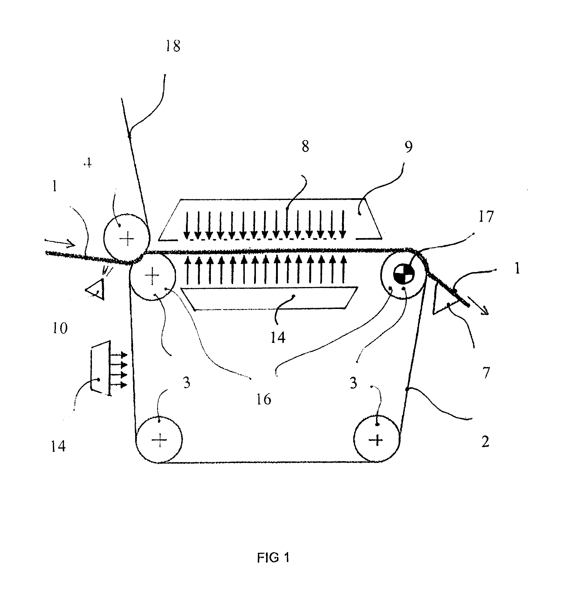
[0042]FIG. 1 shows the invention in which a metal belt 2 conveying a fiber web 1 is arranged rotatable via four rolls 3. In the figure, the delivery of the fiber web 1 is from the left supported by a fabric (e.g. a wire, a felt) to the device where the fiber web 1 transfers to be carried by the metal belt 2 via a nip formed by a pressure roll 4. The delivery of the fiber web 1 can be arranged such that the fiber web 1 is first supported on the shell of the pressure roll 4 directly or the fabric 18 being in between and, then supported by the shell, it transfers to the metal belt 2.

[0043]Before guiding the fiber web 1 to the nip, the fiber web 1 can be wet with a humidifier 10. After the nip, the combined draw of the fiber web 1 and the metal belt can be heated, even on both sides in accordance with the figure. Below the metal belt 2 is heated the metal belt 2, above the fiber web 1 is heated the actual fiber web 1 with air blowings. After the heating stage, the fiber web 1 conveyed b...

second embodiment

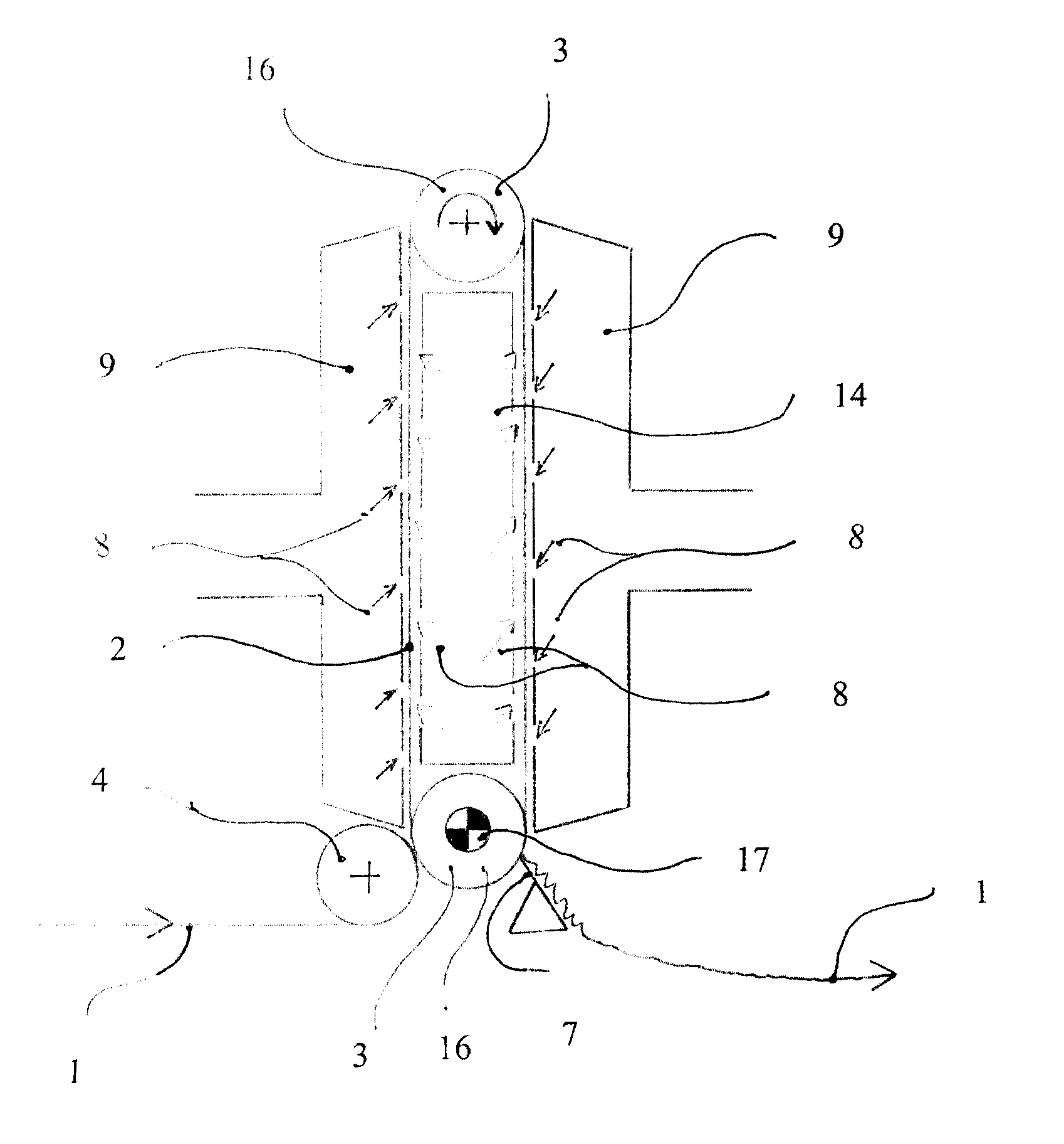
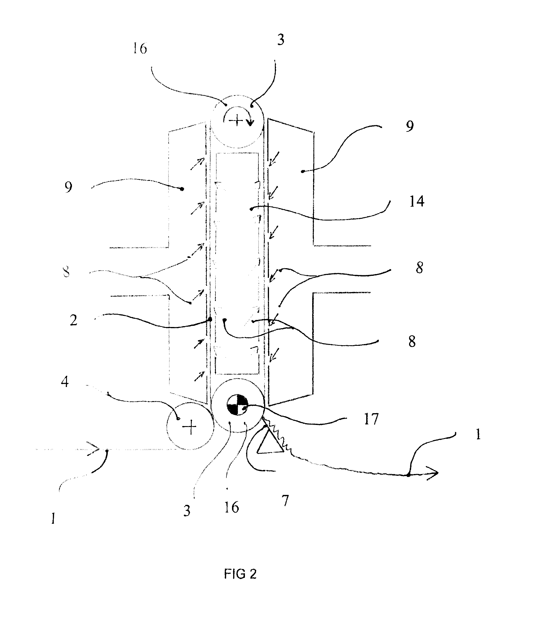
[0045]FIG. 2 shows the invention in which the metal belt cycle is arranged shorter of its principal dimensions in the horizontal direction (machine direction) than in the vertical direction. Thus, the horizontal principal dimension of the cycle of the metal belt 2 is smaller than the vertical principal dimension. The principal dimension refers to the distance between the rotation axes of the outermost rolls 3 in the metal belt cycle in the horizontal or vertical direction. In this arrangement, savings in space are considerable compared to previous in the arrangement based on the yankee cylinder. For heating the fiber web 1 is arranged at least one hood 9 outside the metal belt cycle, whereby the active heating area and travel become very effective. The metal belt cycle is implemented by means of two rolls 3. It is also possible to use three or four rolls 3, whereby the tightening and control operations of the metal belt 2 can be decentralized for different rolls 3. The detachment of...

third embodiment

[0049]FIG. 3 shows the invention in which the fiber web 1 is delivered from the right via a paper guide roll 13 into the nip formed by the metal belt 2 and the pressure roll 4. The fiber web 1 can be first delivered in contact with the metal belt 2 or the shell of the pressure roll 4 from which it is delivered into the nip. Before guiding the fiber web 1 to the nip, the fiber web 1 can be wet with the humidifier 10. Alternatively, moisturising can be applied on the surface of the metal belt 2. The delivery of the fiber web 1 can also be straight from the direction of the tangent to the nip. After the nip formed by the pressure roll 4, the fiber web 1 is supported by the metal belt 2 where it can be heated by means of a hood 9. The hood 9 is advantageously an impingement hood via which it is possible to blow hot air to intensify the drying. The hood 9 can surround the metal belt cycle curvilinearly past the second roll 3 from which the metal belt 2 rotates downwards onto the third ro...


PUM


Abstract

A device for drying and treating a fiber-based moving fiber web (1) in a machine intended for producing tissue paper includes a metal belt (2) which is arranged to support the fiber web (1) and to transfer the fiber web (1) in the machine direction and which metal belt (2) is arranged as a continuous rotating cycle, at least one roll (3) the shell of which is in contact with the metal belt (2) arranged to rotate around, which roll (3) is for supporting and / or controlling the metal belt (2), and at least one counter element (5) arranged to create a contact area outside the metal belt (2) between the metal belt (2) and the counter element (5) for a process zone (6), via which process zone (6) the fiber web (1) is arranged to travel when using the device.

Description

CROSS REFERENCES TO RELATED APPLICATIONS[0001]This application is a U.S. national stage application of International App. No. PCT / FI2010 / 050424, filed May 26, 2010, the disclosure of which is incorporated by reference herein, and claims priority on Finnish App. No. U20090205 filed May 27, 2009.STATEMENT AS TO RIGHTS TO INVENTIONS MADE UNDER FEDERALLY SPONSORED RESEARCH AND DEVELOPMENT[0002]Not applicable.BACKGROUND OF THE INVENTION[0003]The invention relates to a device and a method in the production of a fiber web and particularly relates to a device in the production of a fiber web for drying the fiber web by utilizing a moving metal belt.[0004]An equivalent type of prior art is represented by patent specification WO 03 / 064761 A1 which describes a calender based on a metal belt. This specification can be considered the closest description of prior art.[0005]Furthermore, a prior-art yankee cylinder is depicted in specification U.S. Pat. No. 6,154,981 which describes intensifying th...

Claims


Application Information

Patent Timeline
Patent Type & Authority Patents(United States)
IPC IPC(8): D21F5/18F26B13/04B31F1/14
CPCD21F5/004D21F5/187D21F11/14
Inventor PIETIKAINEN, REIJOHAKOLA, JANIVILJANMAA, MIKAILOMAKI, JARI
Owner VALMET TECH INC
Why Eureka
Try Eureka