Multi-band antenna for simultaneously communicating linear polarity and circular polarity signals

a linear polarity and circular polarity technology, applied in the direction of simultaneous aerial operations, antennas, waveguide horns, etc., can solve the problems of inability to disclose multi-band antennas for simultaneously receiving linear polarity combinations, difficult to design and cost effectively produce and deploy in large quantities, and complex dvbs antenna systems for communicating with satellites

Inactive Publication Date: 2013-07-16
COOK SCOTT
View PDF7 Cites 1 Cited by
  • Summary
  • Abstract
  • Description
  • Claims
  • Application Information

AI Technical Summary

Benefits of technology

[0005]The present invention addresses the needs described above in a variety of multi-band antennas for simultaneously communicating combinations of linear polarity and circular polarity signals. The specific embodiments shown in the figures are designed to receive linear polarity low-band signals simultaneously with circular polarity high-band signals via a single antenna horn structure. Embodiments of the antennas horn structures have circular and oblong cross-sections. In general, strategic location and orientation of low-band and high-band ports with respect to internal ridges that form phase adjustment structures in transition sections and the major and minor axes of the oblong horn allows the antenna to simultaneously manipulate the high-band circular polarity signal without affecting the linear polarity low-band signals. For the horns with circular cross-section, the internal ridges polarize the circular polarity high band signals without assistance from the internal shape of the horn.
[0006]The oblong horn structures are phase adjustment structures configured to differentially phase shift the linear components of the circular polarity high-band signal without affecting the linear polarity low-band signals. For the horns with oblong cross-section, the internal oblong shape of the horn, alone or in combination with internal ridges, polarize the circular polarity high band signals. Over the full length of the antenna horn, the oblong horns and the ridges in combination serve to differentially phase shift and polarize the linear components of the circular polarity high-band signal by approximately 90 degrees to polarize the circular polarity high-band signal into linear components. Most of the embodiments include transition sections with ridges that form phase adjustment structures that operate in combination with the shape of the horn to polarize the circular polarity high-band signals without affecting the linear polarity low-band signals. In certain embodiments, the oblong horn and ridges impart oppositely sloped phase differential sections to improve the high-band gain and bandwidth performance of the antenna as described in U.S. Pat. Nos. 7,239,285 and 7,642,982.

Problems solved by technology

DVBS antenna systems for communicating with satellites are becoming increasingly complex.
These satellites typically operate at different frequency bands and often with different polarities, making the feed assembly challenging to design and cost effectively produce and deploy in large quantities.
Although the antenna technology described in these patents is applicable to DVBS antennas generally, these patents have not disclosed multi-band antennas for simultaneously receiving combinations of linear polarity and circular polarity signals.

Method used


Image

  • Multi-band antenna for simultaneously communicating linear polarity and circular polarity signals
  • Multi-band antenna for simultaneously communicating linear polarity and circular polarity signals
  • Multi-band antenna for simultaneously communicating linear polarity and circular polarity signals

Examples


Embodiment Construction

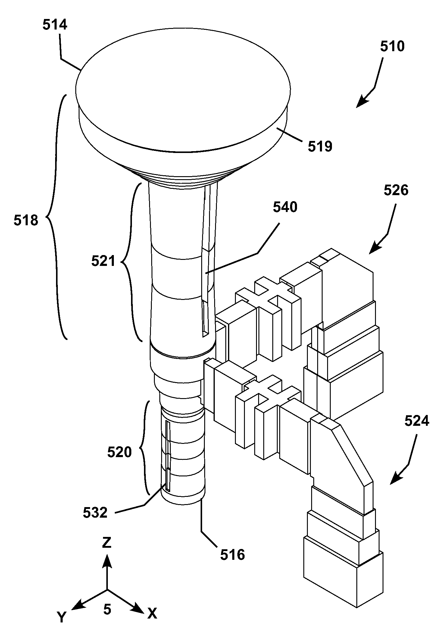
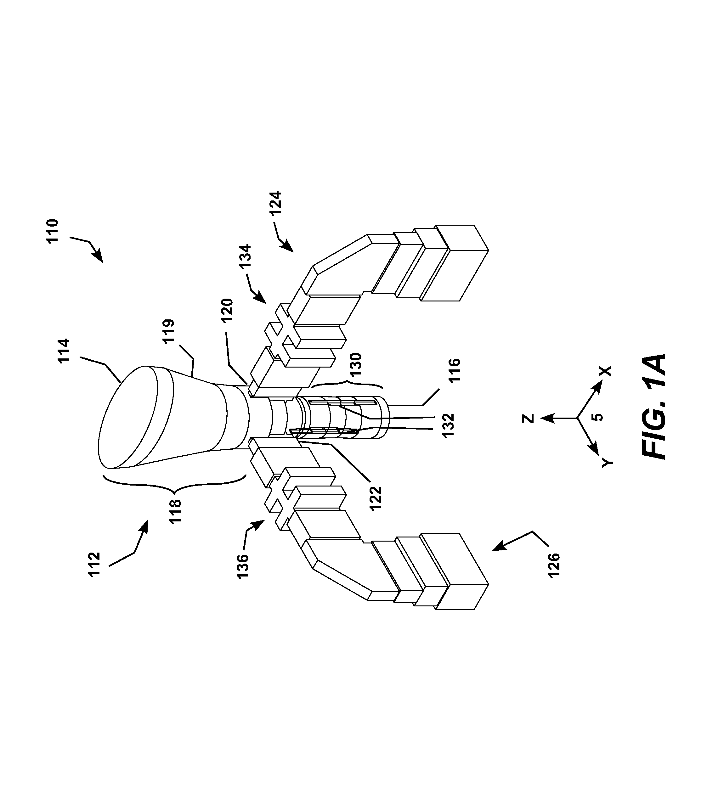
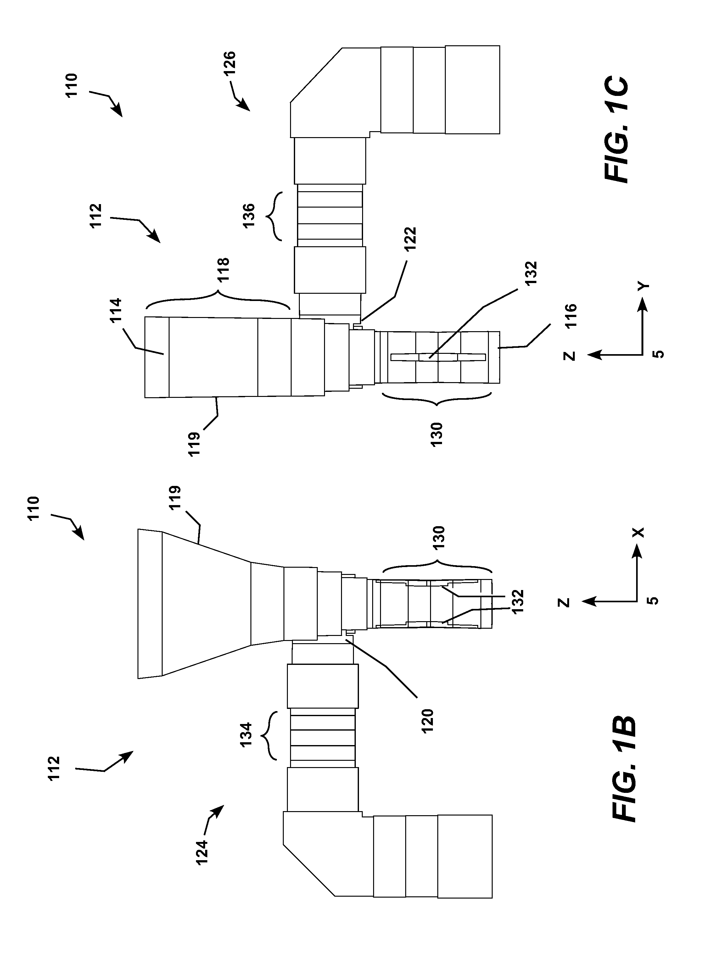
[0051]The present invention may be embodied as improvements to the multi-band DVBS antennas described in U.S. Pat. Nos. 7,239,285 and 7,642,982, which are incorporated herein by reference. These patents teach the use of oppositely sloped phase differential transition sections including various combinations of internal ridges (including septums and corrugations, which are varieties of internal ridges) with oblong and circular horns to improve the bandwidth performance of the antennas. They also disclose multi-band antennas using these techniques for multiple circular polarity signals but do not disclose multi-band antennas for receiving combinations of linear polarity and circular polarity signals. Simultaneously communicating circular and linear polarity signals is challenging because the structures of the antennal must be designed to simultaneously polarize the circular polarity signals without adversely affecting the linear polarity signals. The embodiments of the present inventio...


PUM


Abstract

Multi-band antennas for simultaneously communicating linear polarity low-band signals and circular polarity high-band signals via a single antenna horn structure. The antennas horn structures have circular and oblong cross-sections. Strategic location and orientation of low-band and high-band ports with respect to internal ridges in transition sections and the major and minor axes of the oblong horn allows the antenna to simultaneously manipulate the high-band circular polarity signal without affecting the linear polarity low-band signals. The oblong horn shape and ridges may apply additive or oppositely sloped differential phase shifts to the linear components of the circular polarity high-band signal. For the horns with circular cross-section, the internal ridges may apply additive or oppositely sloped differential phase shifts to polarize the circular polarity high band signals without assistance from the internal shape of the horn.

Description

REFERENCE TO RELATED APPLICATIONS[0001]This application claims priority to commonly-owned copending U.S. Provisional Patent Application Ser. No. 61 / 148,419 entitled “Broad Band and / or Multi-Band Circular and / or Linear Polarity Feed Assembly” filed Jan. 30, 2009, which is incorporated herein by reference.TECHNICAL FIELD[0002]The present invention is generally related to multi-band antenna systems designed to simultaneously receive broadcast signals with circular and linear polarity and, more particularly, is directed to digital video broadcast satellite (DVBS) antenna systems.BACKGROUND OF THE INVENTION[0003]DVBS antenna systems for communicating with satellites are becoming increasingly complex. Quite often a given reflector antenna must be configured to simultaneously receive and transmit signals to multiple satellites. These satellites typically operate at different frequency bands and often with different polarities, making the feed assembly challenging to design and cost effecti...

Claims


Application Information

Patent Timeline
Patent Type & Authority Patents(United States)
IPC IPC(8): H01Q13/00H01Q5/00H01Q5/55
CPCH01P1/17H01Q5/00H01Q13/02H01Q5/55H01Q13/0241H01Q13/0275H01Q15/242H01Q13/0225
Inventor COOK, SCOTT
Owner COOK SCOTT
Why Eureka
Try Eureka