Waterproof operating device with one or more capacitive switches

a capacitive switch and operating device technology, applied in mechanical control devices, process and machine control, instruments, etc., can solve the problems of increased manufacturing cost and delay, o-rings are susceptible to failure, and the conventional configuration of underwater electronic devices cannot resist water pressure up to great depths in water without actuation of switch elements

Inactive Publication Date: 2013-08-27
PIONEER & CO INC
View PDF28 Cites 27 Cited by
  • Summary
  • Abstract
  • Description
  • Claims
  • Application Information

AI Technical Summary

Benefits of technology

[0007]Briefly stated, in its most basic form, the present invention is a waterproof housing for containing and operating an electronic device having a capacitive touch screen and an electrically conductive outer case comprising: a plurality of essentially rigid, interfitting housing pieces forming a waterproof shell configured to removably receive and essentially immobilize the electronic device, a firs...

Problems solved by technology

However, the necessary installation of an O-ring results increased manufacture costs and delay and O-rings are susceptible to failure due to various causes.
However, the conventional configuration of underwater electronic devices ca...

Method used


Image

  • Waterproof operating device with one or more capacitive switches
  • Waterproof operating device with one or more capacitive switches
  • Waterproof operating device with one or more capacitive switches

Examples


first embodiment

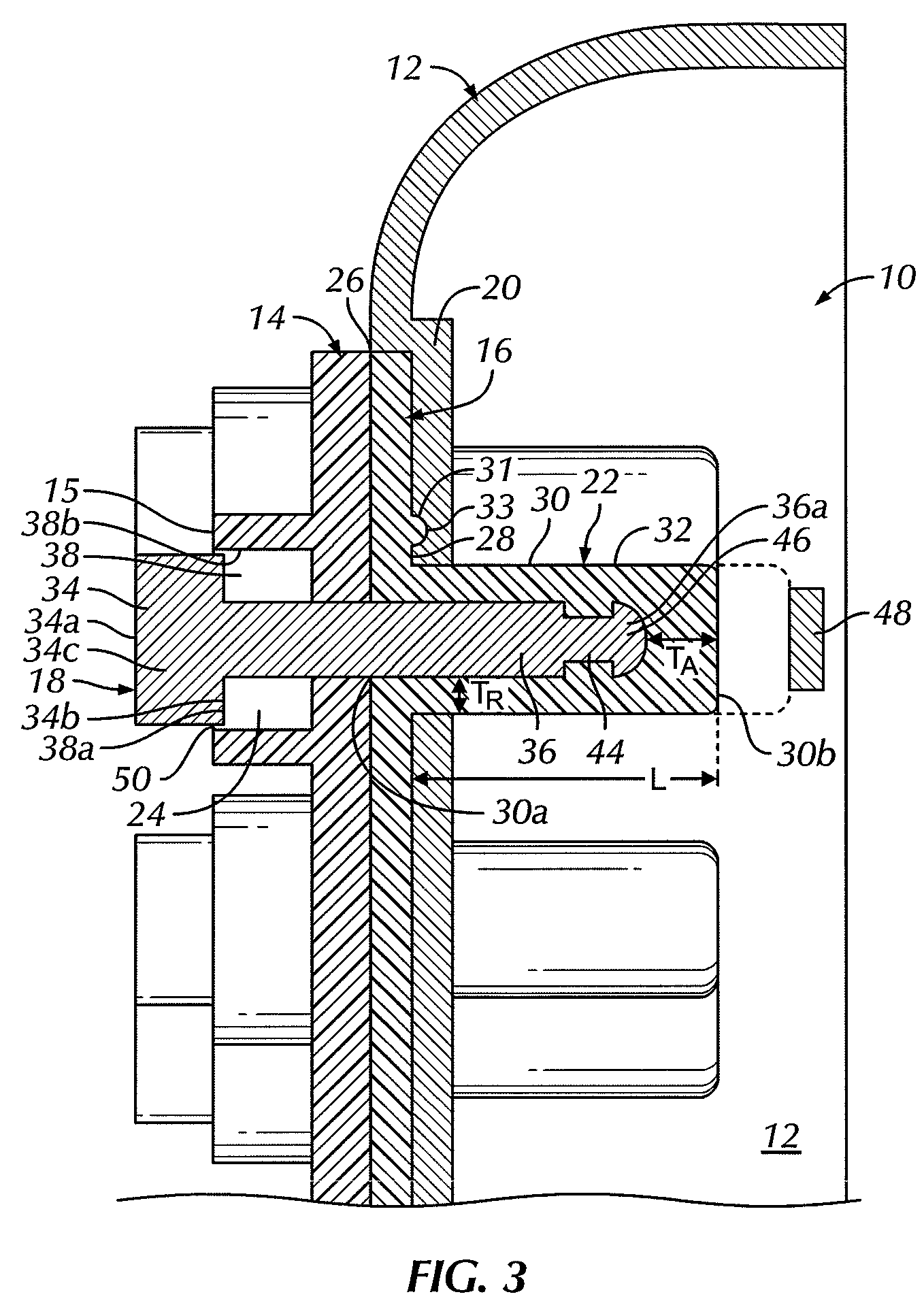
[0041]In an alternative embodiment, shown in FIG. 4, an elastic member 16′ preferably includes a ridge 31′ which extends or protrudes out from a second major surface 28′ of the elastic member 16′ so as to extend around at least a portion of a circumference of each protrusion 30′ and, more particularly, around a circumference of a tubular wall 32′ of each protrusion 30′, closer to the protrusion 30′ than the ridge 31 of the elastic member 16 of the Preferably, the ridge 31′ completely and unbrokenly (i.e., continuously) surrounds the circumference of the protrusion 30′. Where the elastic member 16′ includes a plurality of protrusions 30′, as shown in FIG. 4, the ridge 31′ completely and unbrokenly (i.e., continuously) surrounds the plurality of protrusions 30′, but is still beyond an area that would be covered by the head portion of any buttons received in the protrusions 30′. The ridge 31′ is received within a recessed area (not shown) of a similar size and shape as the ridge 31′. ...

embodiment 112

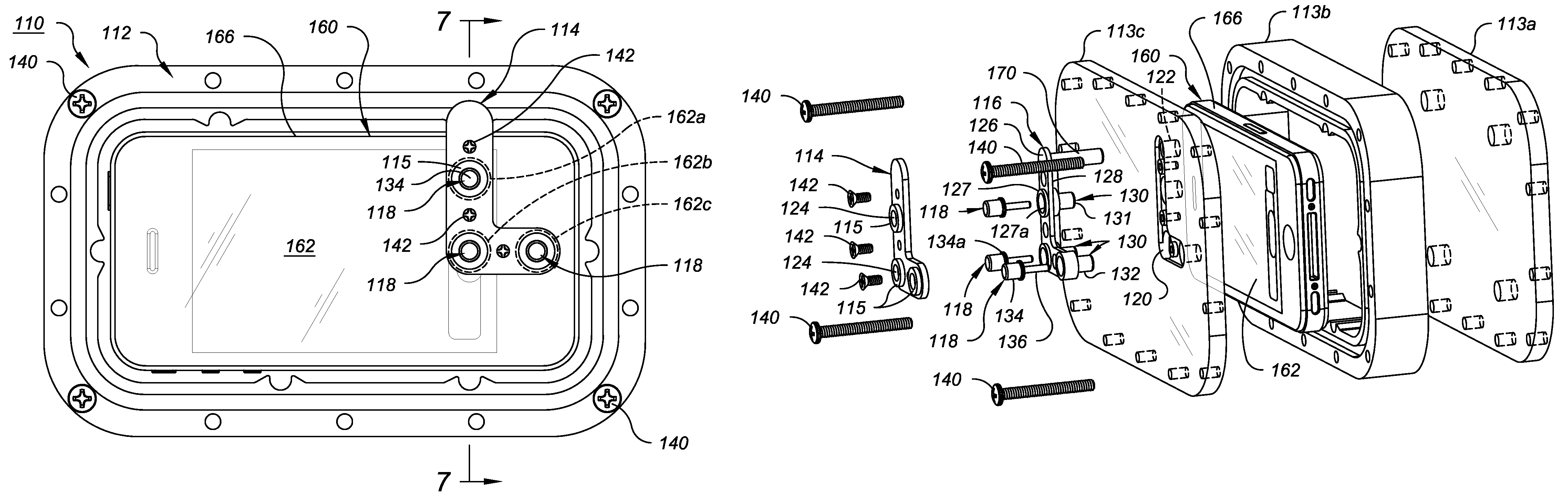
[0064]A plurality of movable buttons 118 are provided on the housing 112 for user inputs to the contained electronic device 160. In the depicted embodiment 112, three identical buttons 118 extend from outside the cover 114 entirely through openings 124, 122 through each of the cover 114 and support surface 120, respectively, and into a separate one of three identical protrusions 130 of the elastic member 116.

[0065]Referring particularly to FIGS. 6 and 7, the configuration of each protrusion 130 is preferably like that of the protrusions 30 of the first embodiment of FIGS. 1-4. Each protrusion 130 extends from the second major surface 128 of the elastic member 116 with an elongated tubular wall 132 and terminates in a closed distal tip 131 directly opposite a separate control region 162a-162c (in phantom in FIG. 5) of the touch screen 162 with the electronic device 160 installed in the housing 112. The distal tip 131 is out of contact with the touch screen 162 while the protrusion 13...

embodiment 110

[0066]Each button 118 is again preferably of the same general configuration as button 18 and has an elongated shaft 136 received within the hollow interior of the tubular wall 132 of the protrusion 130 and a head 134 of larger cross sectional diameter, which is exposed outside the waterproof housing 112 for user manual depression. However, in this embodiment, the head portion 134 includes a radially protruding flange 134a that is larger in diameter than the opening 126 of the cover 114 through which the distal end of the head portion 134 extends and is larger than the smallest diameter of the opening 122 through which its shaft passes through the support surface 120 so as to capture the head portion 134 between the cover 114 and the elastic member 116 / support surface 120. Preferably the cover 114 includes a tubular projection 115 around the button opening 124, forming the opening 124, and an inward facing well 138 having an intermediate diameter larger than that of the opening 124 a...


PUM


Abstract

A waterproof housing to contain and operate an electronic device with capacitive touch screen and electrically conductive outer case includes interfitting pieces configured to form a waterproof shell to removably receive and immobilize the electronic device. One or more electrical circuits extend within the shell between the outer case of the electronic device installed in the shell and one or more respective control regions of the screen. Manual actuators such as buttons are provided in openings through the shell to selectively manually complete each circuit from outside the housing.

Description

CROSS-REFERENCE TO RELATED APPLICATIONS[0001]This application is a continuation-in-part of U.S. application Ser. No. 12 / 717,451 filed Mar. 4, 2010, now U.S. Pat. No. 8,158,899 issued Apr. 17, 2012 and of U.S. patent application Ser. No. 13 / 448,905 filed Apr. 17, 2012, both incorporated by reference in their entirety herein.BACKGROUND OF THE INVENTION[0002]The present invention is directed to a waterproof operating device having superior resistance to water pressure. More particularly, the present invention is directed to a waterproof operating device for use in underwater electronic devices, particularly devices with capacitive switches such as such as the newest generation camera equipped cell phones with capacitive operating touch screens.[0003]Electronic devices designed for underwater use are generally known. Examples of such devices include cameras, watches, computers, hand lights, etc. Often, underwater electronic devices are equipped with one or more buttons for actuation of ...

Claims


Application Information

Patent Timeline
IPC IPC(8): H01H13/06
CPCG06F3/044H01H13/06H01H13/86G06F3/03547H01H2223/003H01H2239/006H01H2231/044H01H2231/046H01H2237/004H01H2231/016
Inventor BLOCH, NATHAN
Owner PIONEER & CO INC
Why Eureka
Try Eureka