

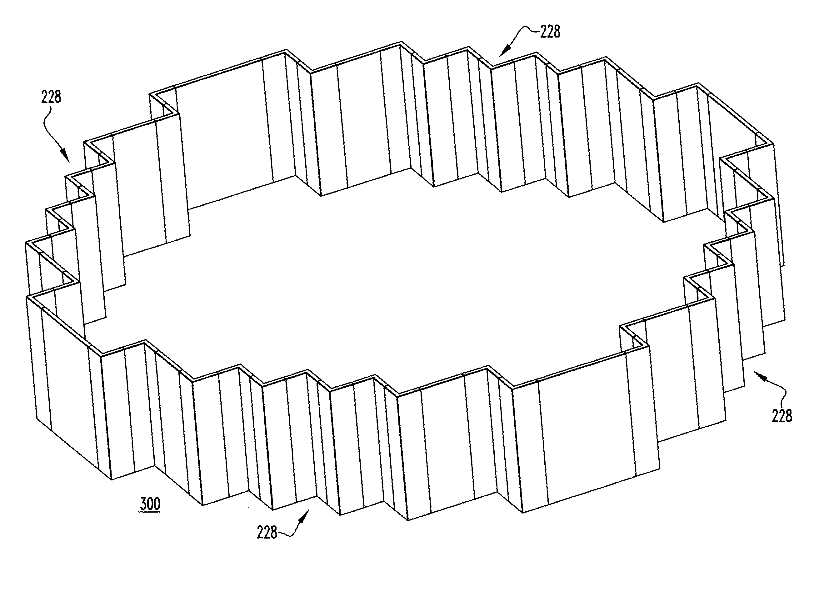
Core shroud corner joints
a corner joint and core shroud technology, applied in the field of core shrouds, can solve the problems of elevated cross-flow velocity and inacceptable fuel rods
- Summary
- Abstract
- Description
- Claims
- Application Information
AI Technical Summary
Problems solved by technology
Method used
Image

Examples
Embodiment Construction
[0038]For purposes of illustration, embodiments of the disclosed concept will be described as applied to core shrouds although it will become apparent that they could also be applied to replace or otherwise eliminate corner joints between joined components of other internals assemblies (e.g., without limitation, battle-former assemblies) to address and overcome problems associated therewith (e.g., without limitation, baffle-jetting).
[0039]Directional phrases used herein, such as, for example, interior, exterior, inside, outside, top, bottom and derivatives thereof, relate to the orientation of the elements shown in the drawings and are not limiting upon the claims unless expressly recited therein.
[0040]As employed herein, the term “unitary” shall mean one single continuous piece of material that is devoid of any seems, joints or connections and which may be formed using any known or suitable method or process such as, for example and without limitation, an extrusion process.
[0041]As...
PUM
 Abstract
Description
Claims
Application Information