Cap for a gas burner

a gas burner and cap technology, applied in the field of cap for gas burners, can solve the problems of fouling of the ignition system, liquids in the cooking vessel or utensil can be heated, extinguishing the flames of the gas burner unit, and spilling

Active Publication Date: 2013-09-17
HAIER US APPLIANCE SOLUTIONS INC
View PDF56 Cites 33 Cited by
  • Summary
  • Abstract
  • Description
  • Claims
  • Application Information

AI Technical Summary

Problems solved by technology

One common problem with gas burner assemblies is that liquids in a cooking vessel or utensil can be heated to such a degree that they may boil over from the top of the cooking vessel and fall onto the cap.
Such boiled-over liquid, referred to as “spillover” or “spill” herein, can extinguish the flames of the gas burner unit and even foul the ignition system.
Moreover, despite efforts with known caps, spillover continues to foul the ignition system because of surface tension between the spillover and the cap as well as dynamics of the spillover.
However, this large cap negatively impacts the combustion of the gas flowing out of the gas discharge ports because the flame has to travel almost horizontally a significant distance under the cap, thereby creating excessive flame impingement.
This substantially reduces the heating efficiency of the gas burner assembly 100.

Method used


Image

  • Cap for a gas burner
  • Cap for a gas burner
  • Cap for a gas burner

Examples


Embodiment Construction

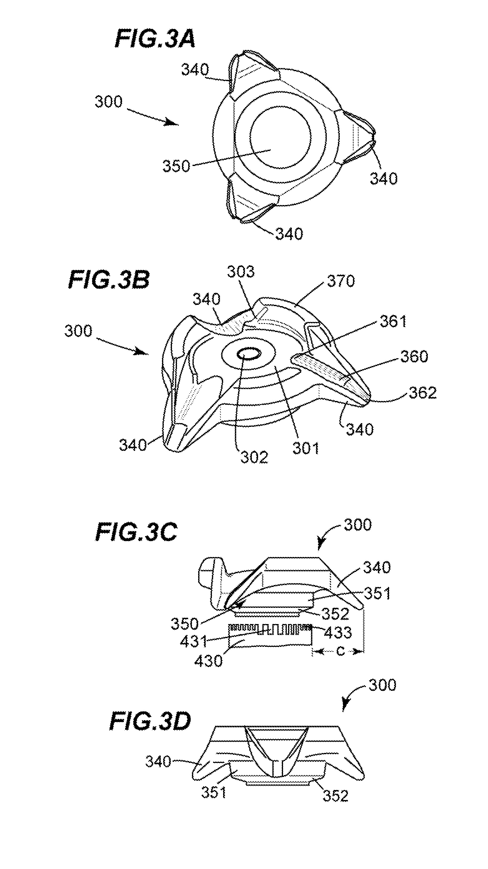
[0020]FIGS. 3A-3D illustrate a bottom view, a perspective view, a first side view, and a second side view, respectively, of a cap 300 in accordance with an exemplary embodiment of the present invention.

[0021]As shown in FIG. 3B, the cap 300 includes a substantially circular main or center portion 301 which has a top surface 302 with a periphery 303. Preferably three extensions or overhangs 340 extend outward and downward from the center portion 301. The extensions 340 are preferably substantially uniformly distributed along the periphery 303.

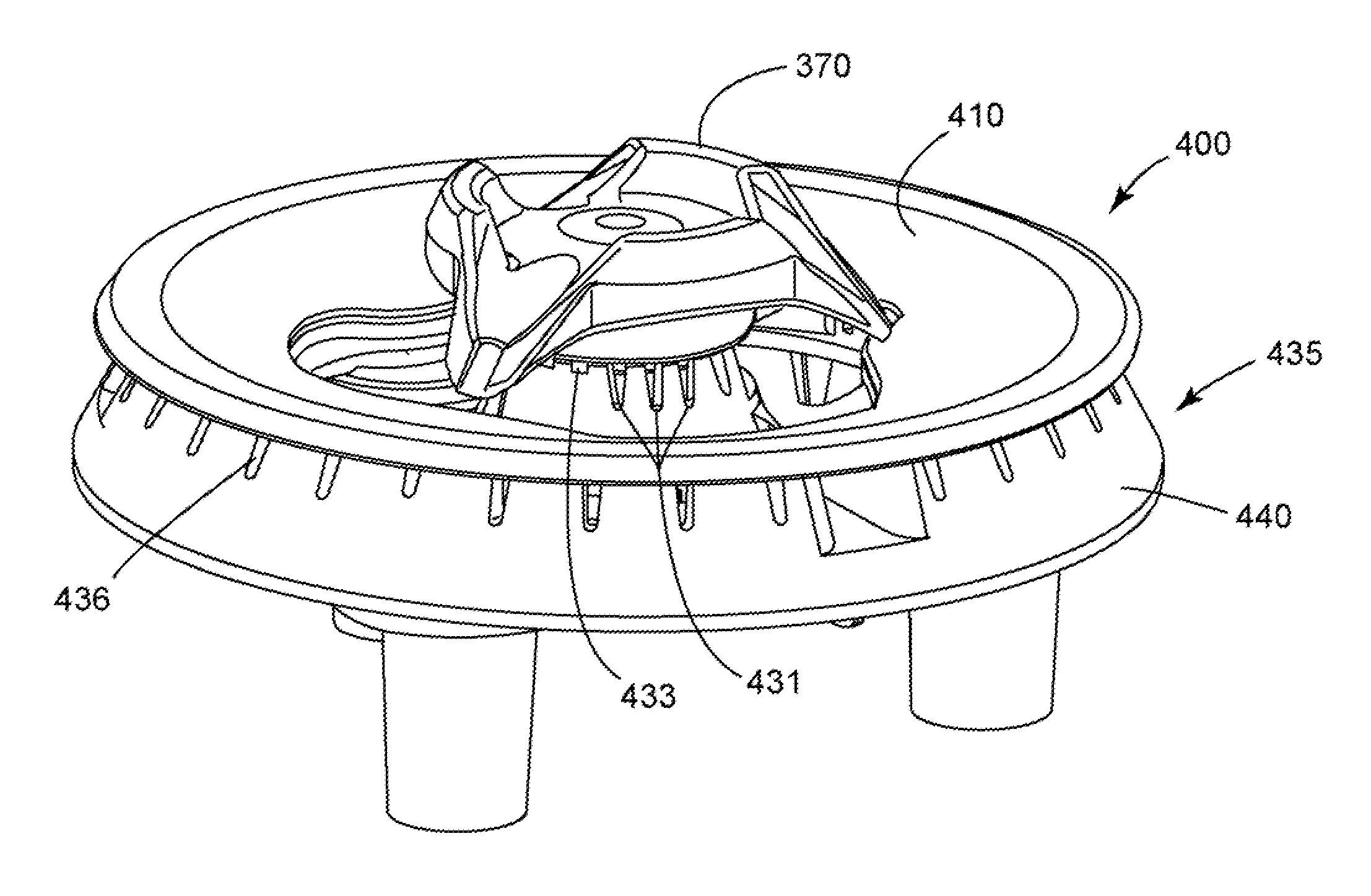
[0022]Each extension 340 defines therein a drain channel 360 which controls or directs the spilled liquids away from the top surface 302 of the center portion 301. More specifically, as illustrated in FIGS. 3B, 3C, 5 and 6, each drain channel 360 extends outward and downward from the top surface 302, with its upper end 361 being terminated at the top surface 302 and its lower end 362 being radially spaced apart from a gas burner unit 430. As cle...


PUM


Abstract

A cap for a gas burner is disclosed. The cap includes a center portion including a top surface having a periphery; at least one extension extending outward from the center portion, the at least one extension defining a drain channel extending outward and downward from the top surface; and a ledge extending along the periphery. A spill resistant gas burner assembly incorporating such a cap is also disclosed.

Description

BACKGROUND OF THE INVENTION[0001]The present invention relates generally to a cap for a gas burner. More particularly, the present invention relates to a cap for a gas burner, and a spill resistant gas burner assembly incorporating such a cap.[0002]Gas burner assemblies have been widely used in cooking appliances such as free standing cooking ranges, cooktop units. Such gas burner assemblies often include a gas burner unit and a cap disposed on the gas burner unit. As is known in the art, included in the gas burner unit is an ignition system, such as, for example, a piezoelectric starter, that provides a spark for igniting gas flowing out of the gas discharge ports of the gas burner unit. Also as is known in the art, the cap can be made an integral part of the gas burner unit. Alternatively, it can be a removable part sitting on the gas burner unit. In the latter configuration, preferably the cap and the gas burner unit together define a plurality of gas discharge ports along a late...

Claims


Application Information

Patent Timeline
Patent Type & Authority Patents(United States)
IPC IPC(8): F24C15/14F23D14/06F24C15/08
CPCF23D14/06F23D14/46F23D2900/14062
Inventor CADIMA, PAUL BRYAN
Owner HAIER US APPLIANCE SOLUTIONS INC
Why Eureka
Try Eureka