Walking device for remedying drop foot

a walking device and foot technology, applied in the field of walking devices, can solve the problems of limiting the mobility difficult concealment under clothing, and many uncomfortable, and achieve the effects of not limiting the mobility or rotation of the foot and ankle of the user, easy concealment, and easy removal

Inactive Publication Date: 2013-10-15
CALDWELL PROD
View PDF21 Cites 12 Cited by
  • Summary
  • Abstract
  • Description
  • Claims
  • Application Information

AI Technical Summary

Benefits of technology

[0012]It is a general object of the present invention to provide a walking device in a compact form so that the walking device may be more easily concealed.
[0013]It is another general object of the present invention to provide a walking device which does not limit the mobility or rotation of a user's ankle.
[0014]It is yet another object of the present invention to provide a walking device can easily be secured and removed from a person's everyday shoe without requiring drastic modifications to the shoe or a special shoe that is made to be compatible with the walking device.

Problems solved by technology

A problem with many prior walking devices is that they are generally large and bulky, making them difficult to conceal under clothing.
Furthermore, many are uncomfortable because they pull on the laces of shoes, or require the user to stand on a plate or other surface, which is inserted into and extends along an insole of a shoe.
Another problem with prior walking devices is that even though prior braces may prevent the person's foot from dragging across the ground, they also limit the mobility of the person's foot and ankle.
That is, many such devices lock the user's ankle such that the foot is at a 90 degree angle with respect to the leg, which prevents the toe from dropping, but does not enable the user to walk naturally.
Yet another problem with prior walking devices is that many require extensive modifications to a person's shoe to secure the brace or require the use of a special shoe made specifically for the walking device.
This drastically limits the selection of shoe styles available to a person with drop foot.
It also prevents a user from being able to put on or take off a walking device at any time desired by the user.

Method used


Image

  • Walking device for remedying drop foot
  • Walking device for remedying drop foot
  • Walking device for remedying drop foot

Examples


Embodiment Construction

[0025]At the outset, it should be appreciated that like drawing numbers on different drawing views identify identical, or functionally similar, structural elements of the invention. While the present invention is described with respect to what is presently considered to be the preferred aspects, it is to be understood that the invention as claimed is not limited to the disclosed aspects.

[0026]Furthermore, it is understood that this invention is not limited to the particular methodology, materials and modifications described and as such may, of course, vary. It is also understood that the terminology used herein is for the purpose of describing particular aspects only, and is not intended to limit the scope of the present invention, which is limited only by the appended claims.

[0027]Unless defined otherwise, all technical and scientific terms used herein have the same meaning as commonly understood to one of ordinary skill in the art to which this invention belongs. It should be appr...


PUM


Abstract

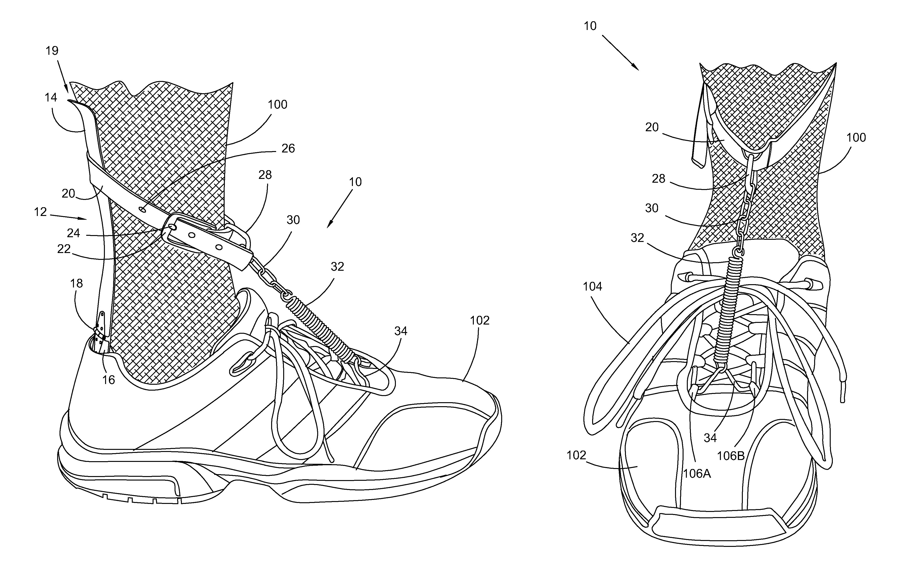
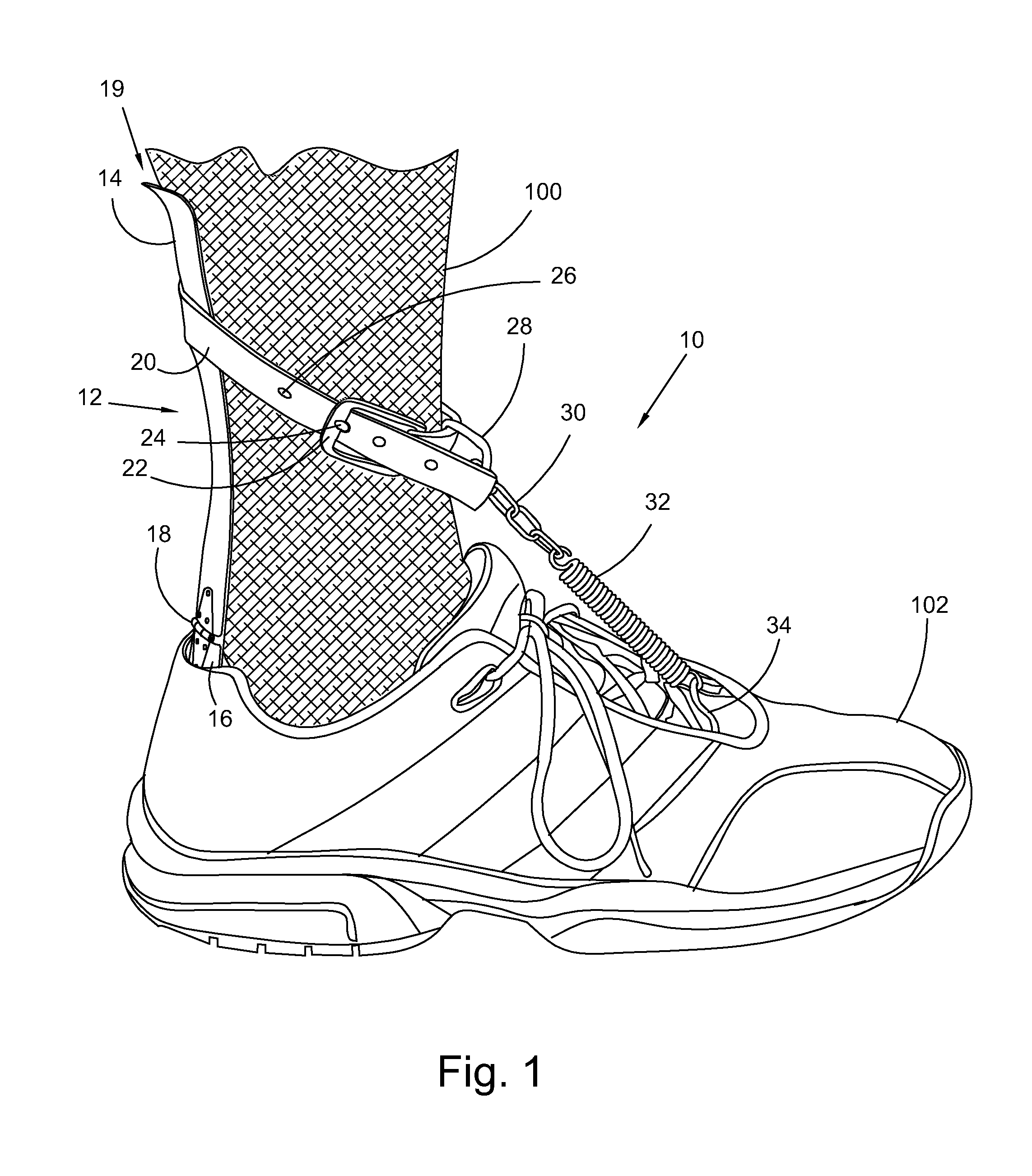
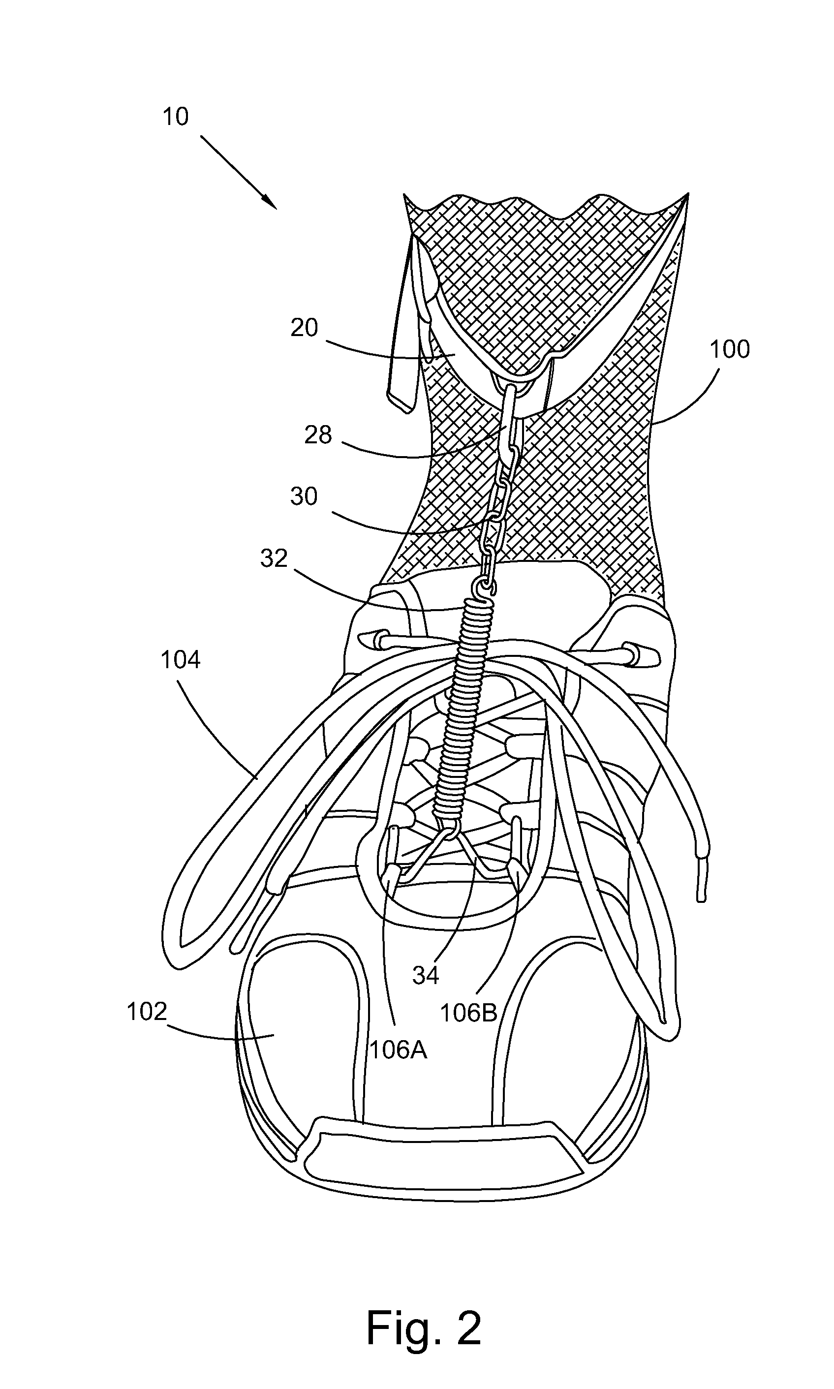
A walking device for remedying or alleviating symptoms of drop foot, the device wearable with an article of footwear, the device including a backing plate, wherein the backing plate includes an upper portion hingedly secured to a lower portion, a strap secured to the upper portion of the backing plate and extending outwardly therefrom for operatively securing to itself about a leg of a person, a spring including a first end secured to the strap, and a clip secured to a second end of the spring, wherein the clip is operatively arranged to engage with a pair of eyelets for laces of the footwear.

Description

FIELD OF THE INVENTION[0001]The invention broadly relates to a walking device, and more specifically, to a device to alleviate drop foot.BACKGROUND OF THE INVENTION[0002]Drop foot is a neuromuscular disorder characterized by the inability or difficulty of a person to move the ankle and / or lift the toes upward. This particular type of movement is referred to as dorsiflexion. Because of the lack of dorsiflexion, the person with drop foot often drags his foot and toes while walking. Drop foot is also commonly referred to as foot drop.[0003]Some walking aids or devices to alleviate drop foot are known in the art, which provide the person with the ability to control the person's foot to prevent it from dragging across the ground. A problem with many prior walking devices is that they are generally large and bulky, making them difficult to conceal under clothing. Furthermore, many are uncomfortable because they pull on the laces of shoes, or require the user to stand on a plate or other s...

Claims


Application Information

Patent Timeline
Patent Type & Authority Patents(United States)
IPC IPC(8): A61F5/00
CPCA61F5/0113
Inventor CALDWELL, STEVENCALDWELL, MICHAEL J.
Owner CALDWELL PROD
Why Eureka
Try Eureka