System and method for magnetic resonance radio-frequency field mapping

a radiofrequency field and system technology, applied in the field of magnetic resonance imaging, can solve the problems of limiting the clinical application of such techniques at a high magnetic field, relying on a relatively long repetition time, and other techniques that are inaccurate over certain ranges of the bsub>1 /sub>field

Active Publication Date: 2013-10-15
GENERAL ELECTRIC CO
View PDF10 Cites 12 Cited by
  • Summary
  • Abstract
  • Description
  • Claims
  • Application Information

AI Technical Summary

Problems solved by technology

Still other techniques are inaccurate over certain ranges of the B1 field, and / or are dependent on large RF power depositions.
Although such a technique is more accurate than other techniques over a larger range of flip angles, such a technique is B0 dependent and often relies on a relatively long repetition time (TR).
However, the specific absorption rate (SAR) associated with such techniques can limit the clinical application of such techniques at a high magnetic field.
Thus, conventional techniques for B1 mapping may have limitations over particular field ranges or require properties that limit the clinical applications of such methods.

Method used


Image

  • System and method for magnetic resonance radio-frequency field mapping
  • System and method for magnetic resonance radio-frequency field mapping
  • System and method for magnetic resonance radio-frequency field mapping

Examples


Embodiment Construction

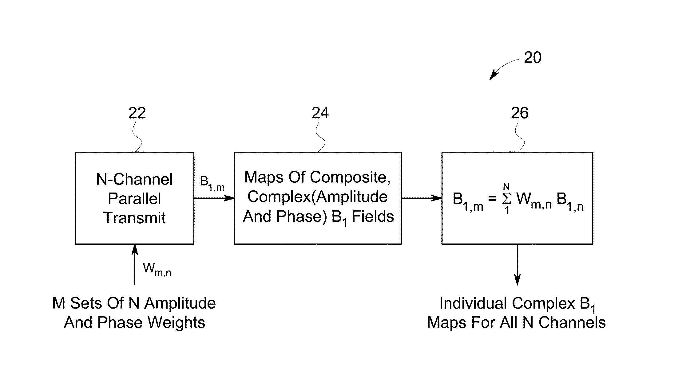
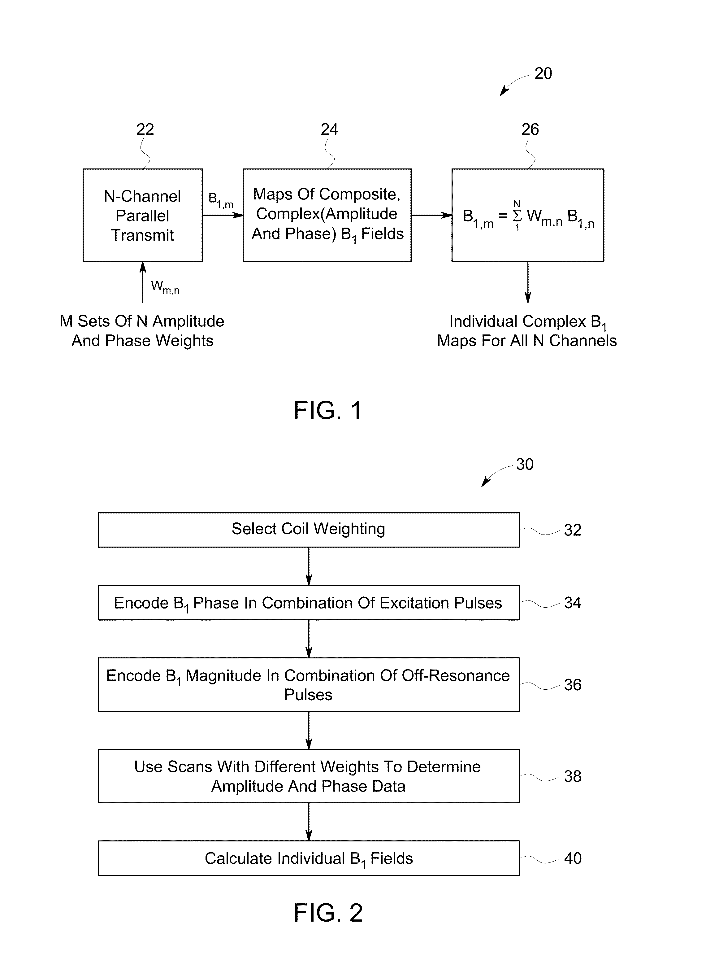
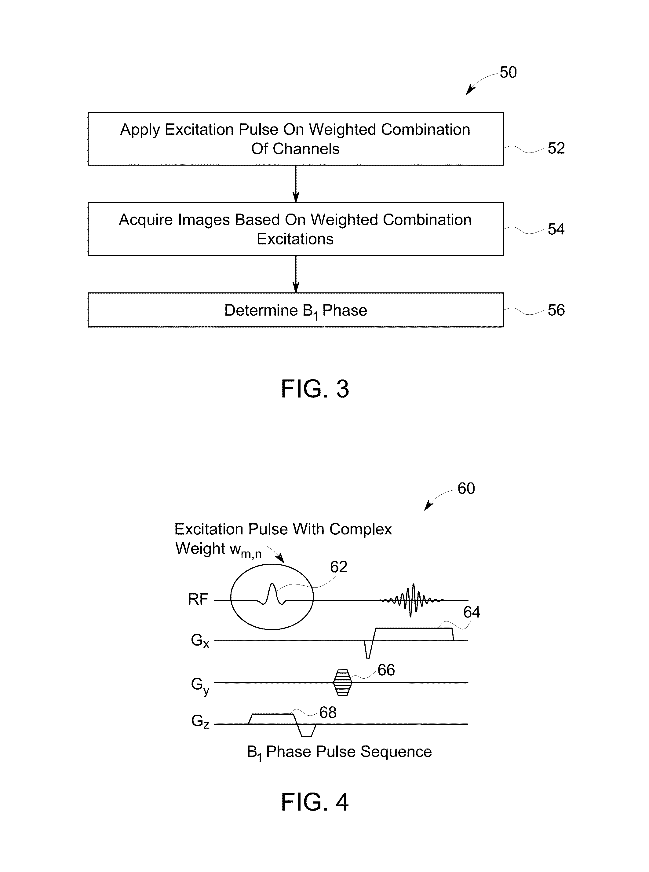
[0026]The foregoing summary, as well as the following detailed description of certain embodiments, will be better understood when read in conjunction with the appended drawings. To the extent that the figures illustrate diagrams of the functional blocks of various embodiments, the functional blocks are not necessarily indicative of the division between hardware. Thus, for example, one or more of the functional blocks may be implemented in a single piece of hardware or multiple pieces of hardware. It should be understood that the various embodiments are not limited to the arrangements and instrumentality shown in the drawings. Additionally, the system blocks in the various figures or the steps of the methods may be rearranged or reconfigured. Also, the steps of the various methods may be modified and performed in a different order or repeated as desired or needed.

[0027]As used herein, an element or step recited in the singular and proceeded with the word “a” or “an” should be underst...


PUM


Abstract

A system and method for radio-frequency (RF) field mapping are provided. One method includes encoding a B1 phase in at least one magnetic resonance (MR) excitation pulse as an encoded B1 phase MR excitation pulse for at least a subset of a plurality of transmit channels within a magnetic resonance imaging (MRI) system. The method also includes encoding a B1 magnitude in at least one off-resonance MR pulse as an encoded B1 magnitude off-resonance MR pulse for at least a subset of the plurality of transmit channels within the MRI system. The method further includes determining one or more composite B1 fields resulting from a transmission of the at least one encoded B1 phase MR excitation pulse and the at least one encoded B1 magnitude off-resonance MR pulse.

Description

BACKGROUND[0001]The subject matter disclosed herein relates generally to magnetic resonance imaging (MRI) systems, and more particularly to systems and methods for mapping radio-frequency (RF) fields for MRI systems having multiple transmit channels.[0002]MRI or Nuclear Magnetic Resonance (NMR) imaging generally provides for the spatial discrimination of resonant interactions between RF waves and nuclei in a magnetic field. Specifically, MRI utilizes hydrogen nuclear spins of the water molecules in the human body, which are polarized by a strong, uniform, static magnetic field of a magnet. This magnetic field is commonly referred to as B0 or the main magnetic field. When a substance, such as human tissue, is subjected to the main magnetic field, the individual magnetic moments of the spins in the tissue attempt to align with the main magnetic field. MRI data acquisition is accomplished by exciting magnetic moments within the primary magnetic field using transmit RF coils. In particu...

Claims


Application Information

Patent Timeline
Patent Type & Authority Patents(United States)
IPC IPC(8): G01V3/00
CPCG01R33/246G01R33/5612
Inventor SACOLICK, LAURA IRENEVOGEL, MIKAGRISSOM, WILLIAMKUDIELKA, GUIDO
Owner GENERAL ELECTRIC CO
Why Eureka
Try Eureka