
Velocity Vector Field Mapping Using Electrical Capacitance Sensors

a capacitance sensor and velocity vector technology, applied in the direction of instruments, fluid speed measurement, liquid/fluent solid measurement, etc., can solve the problems of instruments suffering from different shortcomings, simulations that do not completely capture the physical world, and extremely complex fluid mechanics studies

Active Publication Date: 2017-08-24
TECH4IMAGING +1
View PDF7 Cites 12 Cited by
  • Summary
  • Abstract
  • Description
  • Claims
  • Application Information

AI Technical Summary

Benefits of technology

The patent text discusses how important it is to measure the speed at which a fluid is flowing in a certain area or volume. This can help calculate things like the strain rate and the amount of heat or mass transfer that is happening. This is challenging because fluid mechanics involves interactions at the molecular and particle levels. The text then explains how non-invasive tools like velocimetry can help shed light on the behavior of flows and control processes that are influenced by fluid motions.

Problems solved by technology

Studying fluid mechanics is extremely challenging and complex as it involves interactions on the molecular and particle levels.
However, those simulations do not completely capture the physical world and require a validation method through instantaneous visualization of fluid vector fields, including velocity.
Nevertheless, such instruments suffer from different shortcomings as many of them attempt to predict the velocity profile from following a few tracer particles.
Moreover, the applicability of such techniques is often restricted to laboratory environment as used sensors are usually fragile.
However, the velocity profile found by this method is different from true flow velocity which can be quite complicated.
This method is often restricted to measuring average velocity of a flow instead of mapping a vector velocity profile.
However, cross-correlation of volume images poses two main obstacles: First, it is computationally intensive and cannot be applied for real-time velocity profiling applications.
Second, the velocity profile lacks accuracy as any error from the image reconstruction process contaminates any subsequent calculations of velocity profiling based on cross-correlation since the images are used as inputs to the calculation process.
Consequently, the complexity of reconstruction of the present approach to determine the velocity profile is much lower than the cross-correlation velocimetry and similar to that of conventional ECT / ECVT / AECVT permittivity profile reconstruction (i.e., Linear Back Projection and Landweber Iteration).

Method used


Image

  • Velocity Vector Field Mapping Using Electrical Capacitance Sensors
  • Velocity Vector Field Mapping Using Electrical Capacitance Sensors
  • Velocity Vector Field Mapping Using Electrical Capacitance Sensors

Examples


Embodiment Construction

)

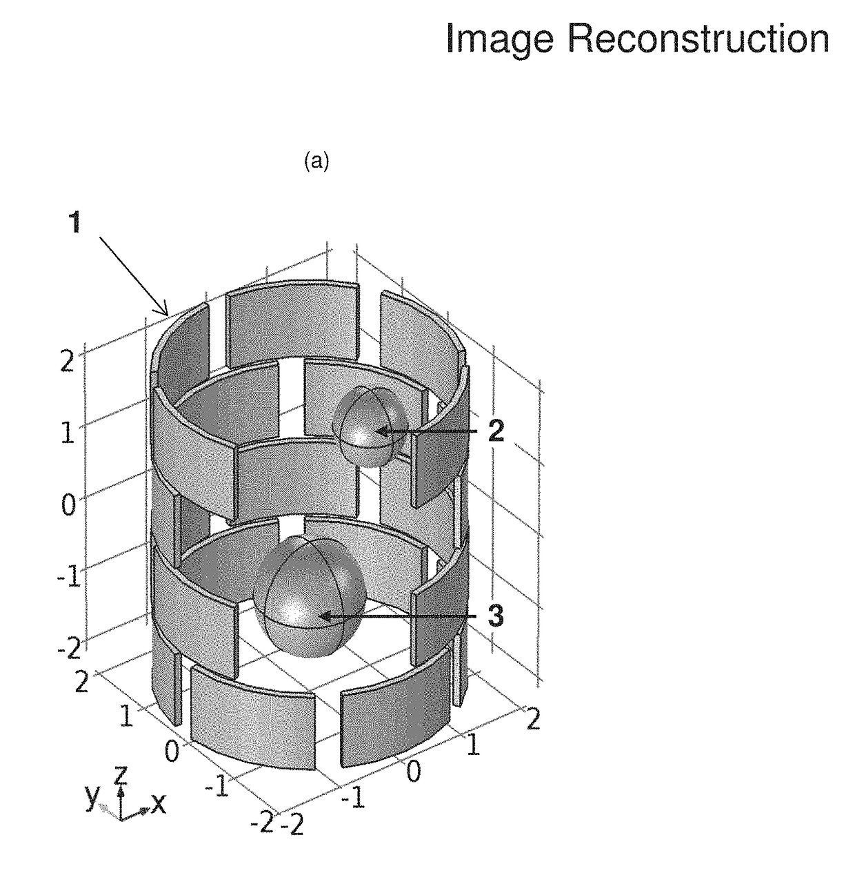
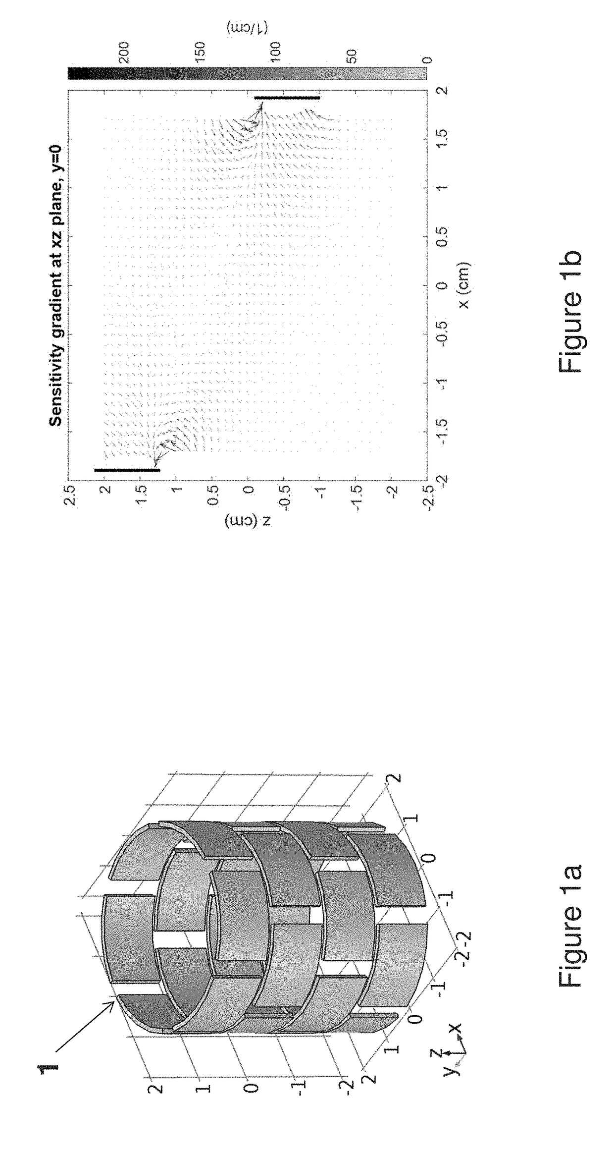
[0016]FIG. 1a illustrates a typical 24 electrode ECVT sensor (1) with 4 planes of plates. FIG. 1b illustrates a sensitivity gradient at the xz plane between an opposite pair of electrodes at two different planes. The sensitivity gradient map is obtained by applying a gradient operator to the sensitivity map of the ECVT sensor.

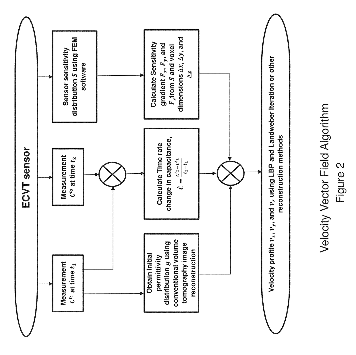
[0017]FIG. 2 illustrates a flow chart of on embodiment of the velocity algorithm for vector field mapping of velocity at each voxel location. A voxel is a 3D pixel. Pixels are usually used for 2D discretization of a surface, and voxel is for 3D of a volume. Capacitance frames are acquired at different times and used to calculate the time derivative of capacitance from the known frame rate of the data acquisition. Frame is one set of capacitance measurements that are used to reconstruct one image. Frame rate is the number of capacitance sets that are produced by the acquisition system per second. This is also the maximum number of images that can be reconstruct...


PUM


Abstract

The present invention provides a system and method for velocity vector field calculation at the voxel level of a multi-phase flow system using Electrical Capacitance Volume Tomography sensors.

Description

BACKGROUND AND SUMMARY OF THE INVENTIVE FIELD[0001]Velocimetry is the process of providing instantaneous velocity vector measurements of a flow in a cross-section or volume. In fluid dynamics, measurements of velocity vector fields are important as it can be used to calculate derivative quantities such as rate of strain, and integral quantifies such as fluxes. Studying fluid mechanics is extremely challenging and complex as it involves interactions on the molecular and particle levels. Non-invasive tools that can help shed a light on flow behavior resulting from such interactions between flow components are very valuable. In many engineering problems, heat and mass transfer processes are strongly controlled by fluid motions. Understanding the fluid motion can help control such processes.[0002]Computational Fluid Dynamics (CFD) techniques are often used to simulate flow behavior. However, those simulations do not completely capture the physical world and require a validation method t...

Claims


Application Information

Patent Timeline
Patent Type & Authority Applications(United States)
IPC IPC(8): G01F1/58G01F1/64
CPCG01F1/64G01F1/584G01P5/001G01P5/26
Inventor MARASHDEH, QUSSAITEIXEIRA, FERNANDOCHOWDHURY, SHAH
Owner TECH4IMAGING
Learn More