
Belowground tree anchoring apparatus and method

a technology for anchoring apparatus and trees, applied in the field of anchoring devices for trees, can solve the problems of excessive leaning or falling of trees on the ground, affecting the safety of passing traffic, and using stakes and man-wire systems

Inactive Publication Date: 2013-10-29
FARMER SARAH E +1
View PDF25 Cites 5 Cited by
  • Summary
  • Abstract
  • Description
  • Claims
  • Application Information

AI Technical Summary

Benefits of technology

The system provides safe and effective tree support without exposing hazardous materials above ground, allowing for proper root development and minimizing visual impact while preventing trunk damage, thus enhancing tree stability and appearance.

Problems solved by technology

Strong winds and excessive moisture can cause a poorly supported tree to lean excessively or fall to the ground.
However, there are several disadvantages associated with using stakes and guy wire systems.
The stakes and guy wires are typically exposed above grade level of the ground, and can pose hazards to passing traffic, such as pedestrians, children, and to ground maintenance equipment, such as lawnmowers and the like.
Typical above ground staking increases the likelihood of weedeater or herbicide use at the base of the tree, which can be harmful to young, tender trees.
The presence of these components is also visually displeasing and often undesirably detracts from the appearance of the tree or shrub and the surrounding area.
Perhaps most importantly, such guy wires can cause damage to the trees themselves by digging into the trunk of the tree and creating weak spots that prevent the tree from growing properly.
Oftentimes the tree will begin to grow normally above the anchor point, but have an underdeveloped lower trunk, resulting in a weakened tree that is prone to falling.

Method used


Image

  • Belowground tree anchoring apparatus and method
  • Belowground tree anchoring apparatus and method
  • Belowground tree anchoring apparatus and method

Examples


Embodiment Construction

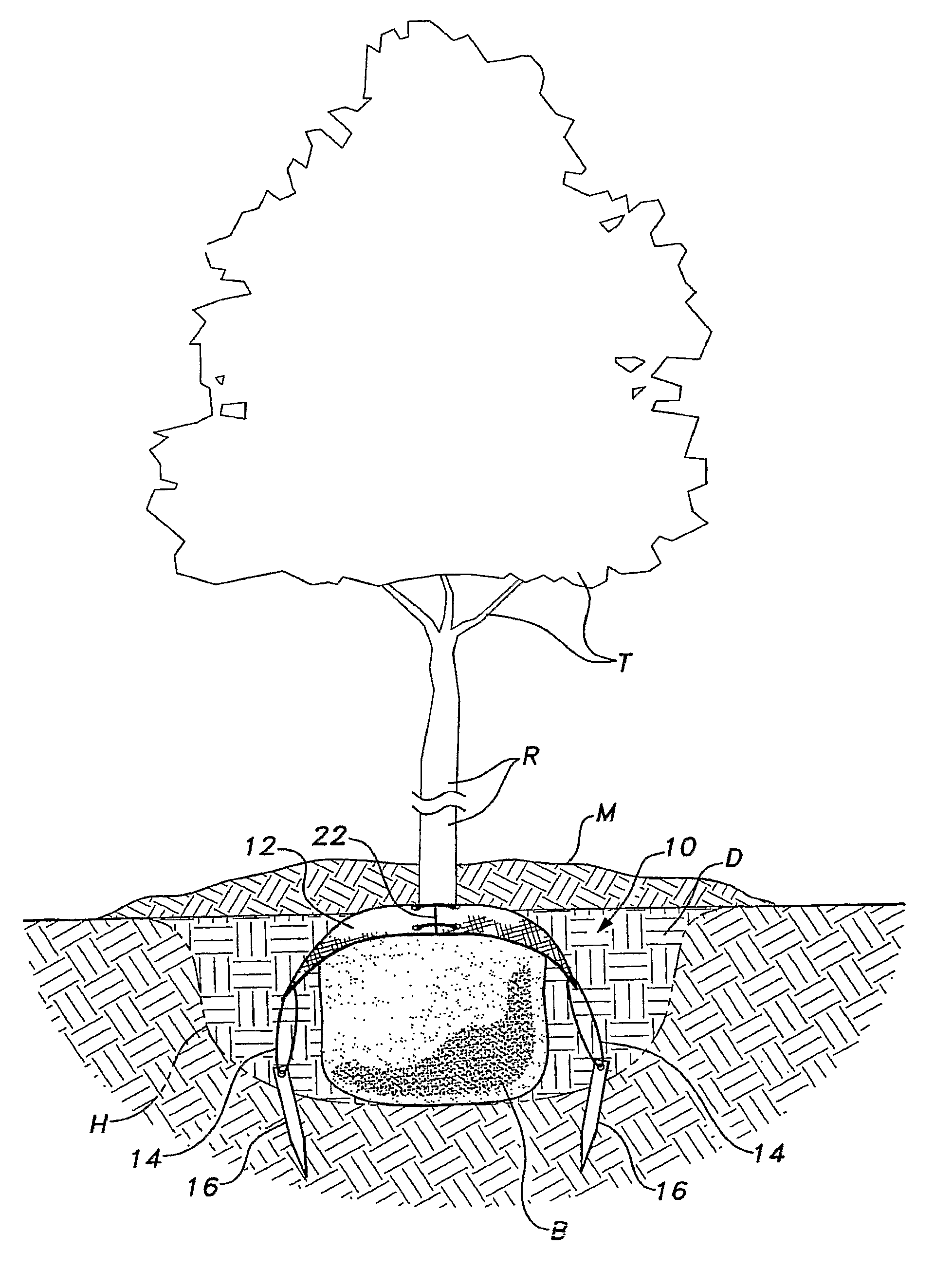
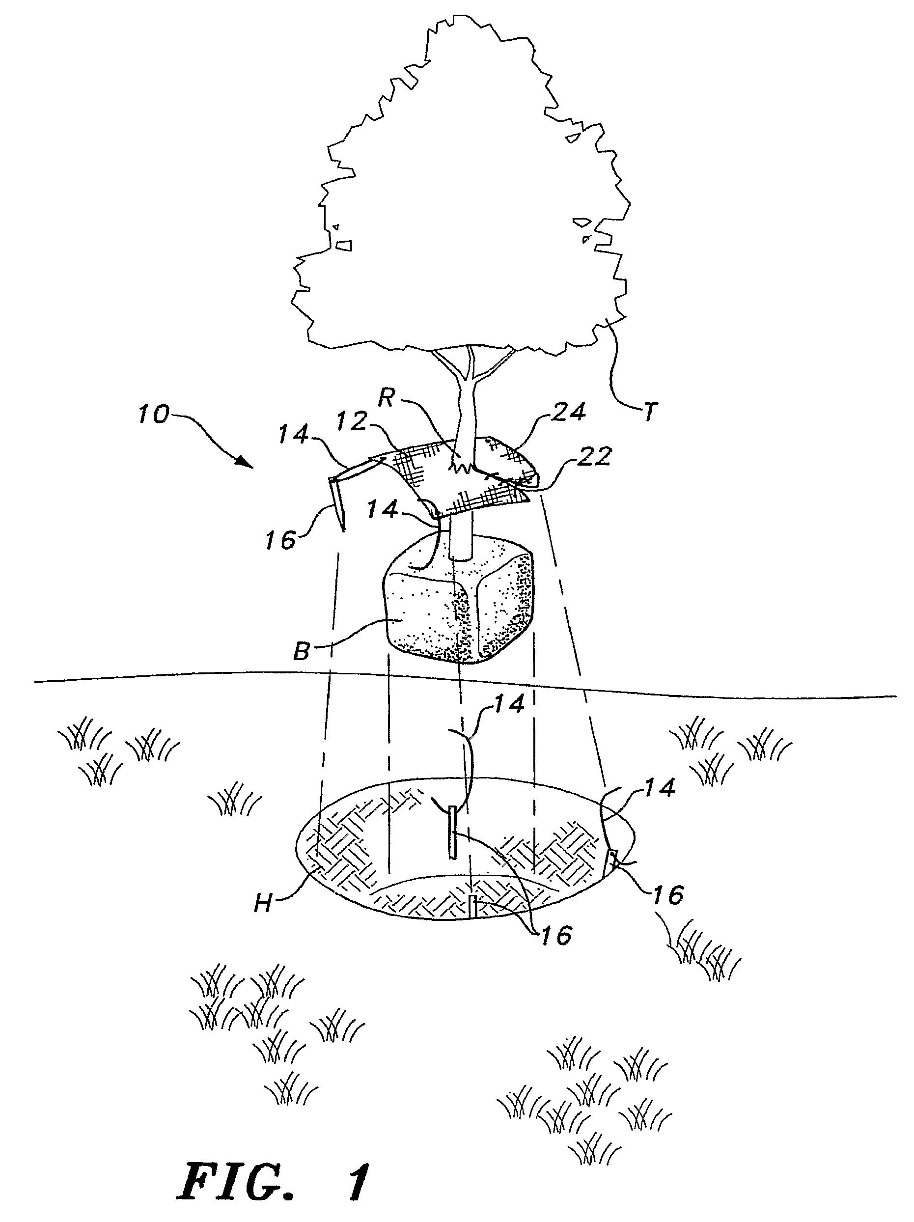
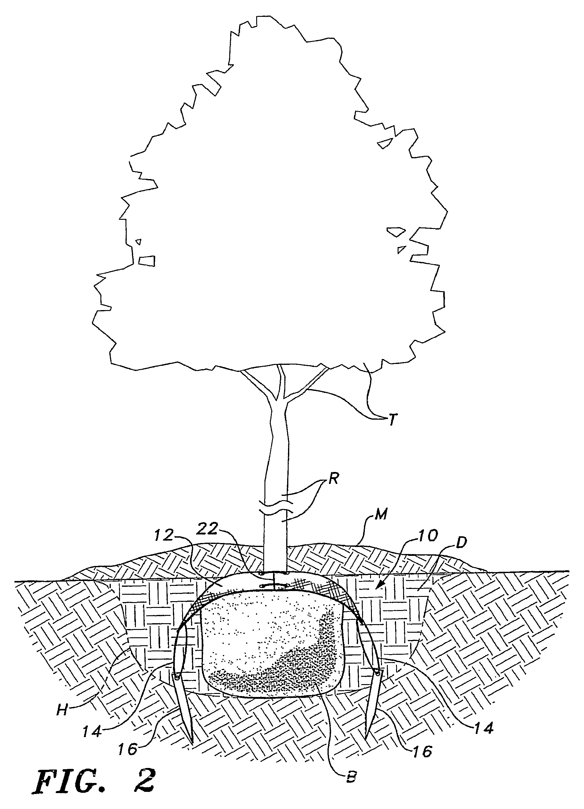
[0015]The belowground tree anchoring apparatus is used for anchoring a tree at the time of planting and includes a flexible blanket, a plurality of stakes, and a plurality of ties. The blanket is configured to fit over the root ball at the base of the trunk of the tree and has a center opening defined by a hole or by short radial slits extending from the center, and an elongated radial slit extending to the periphery for facilitating this arrangement. The blanket is also equipped with a plurality of anchor holes (which may be protected by grommets) that are disposed in the periphery of the blanket, and fasteners for securing the two edges of the elongated slit together once the blanket has been applied about the trunk of the tree.

[0016]The stakes are provided for securing the apparatus to the ground. Each of the stakes is connected to the blanket by ties, each tie being attached to the blanket at one of the peripheral anchor holes. Each of the stakes is driven into the ground far en...


PUM


Abstract

The belowground tree anchoring apparatus (10) includes a blanket (12), a plurality of stakes (16), and a plurality of ties (14). The blanket (12) fits over the root ball (B) at the base of the trunk (R) of the tree (T) and has a center opening and an elongated, radial slit (22) for facilitating this arrangement. The blanket (12) has a plurality of peripheral tie attachment holes, which may be reinforced with grommets. The stakes (16) are driven into the planting hole (H) at the bottom of the hole (H), and each stake (16) is connected to the blanket by a tie (14), and each tie (14) is attached to the blanket (12) at one of the peripheral grommets. When the ties (14) are fully tensioned, the blanket (12) holds the root ball (B) tightly to the ground.

Description

CROSS-REFERENCE TO RELATED APPLICATION[0001]This application is a 371 of PCT / US07 / 00767, filed Jan. 12, 2007 which claims the benefit of U.S. Provisional Patent Application Ser. No. 60 / 772,903, filed Feb. 14, 2006.TECHNICAL FIELD[0002]The present invention relates to arboreal anchoring devices, and more specifically to a belowground tree anchoring apparatus and method.BACKGROUND ART[0003]Typically newly planted trees initially require some level of assisted support to prevent tilting or toppling. Strong winds and excessive moisture can cause a poorly supported tree to lean excessively or fall to the ground. Adequate support enhances the survival of the tree during the critical growth period. The support is usually maintained until the roots have sufficiently established themselves in the ground.[0004]Conventional methods for supporting trees typically include driving two or more stakes into the ground adjacent to the trunk of the tree and tethering the trunk to the stakes with guy w...

Claims


Application Information

Patent Timeline
Patent Type & Authority Patents(United States)
IPC IPC(8): A01G13/02
CPCA01G17/04A01G13/0293
Inventor FARMER, SARAH E.FARMER, JAMES W.
Owner FARMER SARAH E
Learn More