Differential signal transmission cable
a transmission cable and signal technology, applied in the direction of power cables, cables, insulated conductors, etc., can solve the problems of differential mode to common mode conversion amount increase, metal foil tape slack, etc., and achieve the effect of suppressing skew and differential mode to common mode conversion amoun
- Summary
- Abstract
- Description
- Claims
- Application Information
AI Technical Summary
Benefits of technology
Problems solved by technology
Method used
Image
Examples
first embodiment
[0032](Outline of a Structure of a Differential Signal Transmission Cable 1)
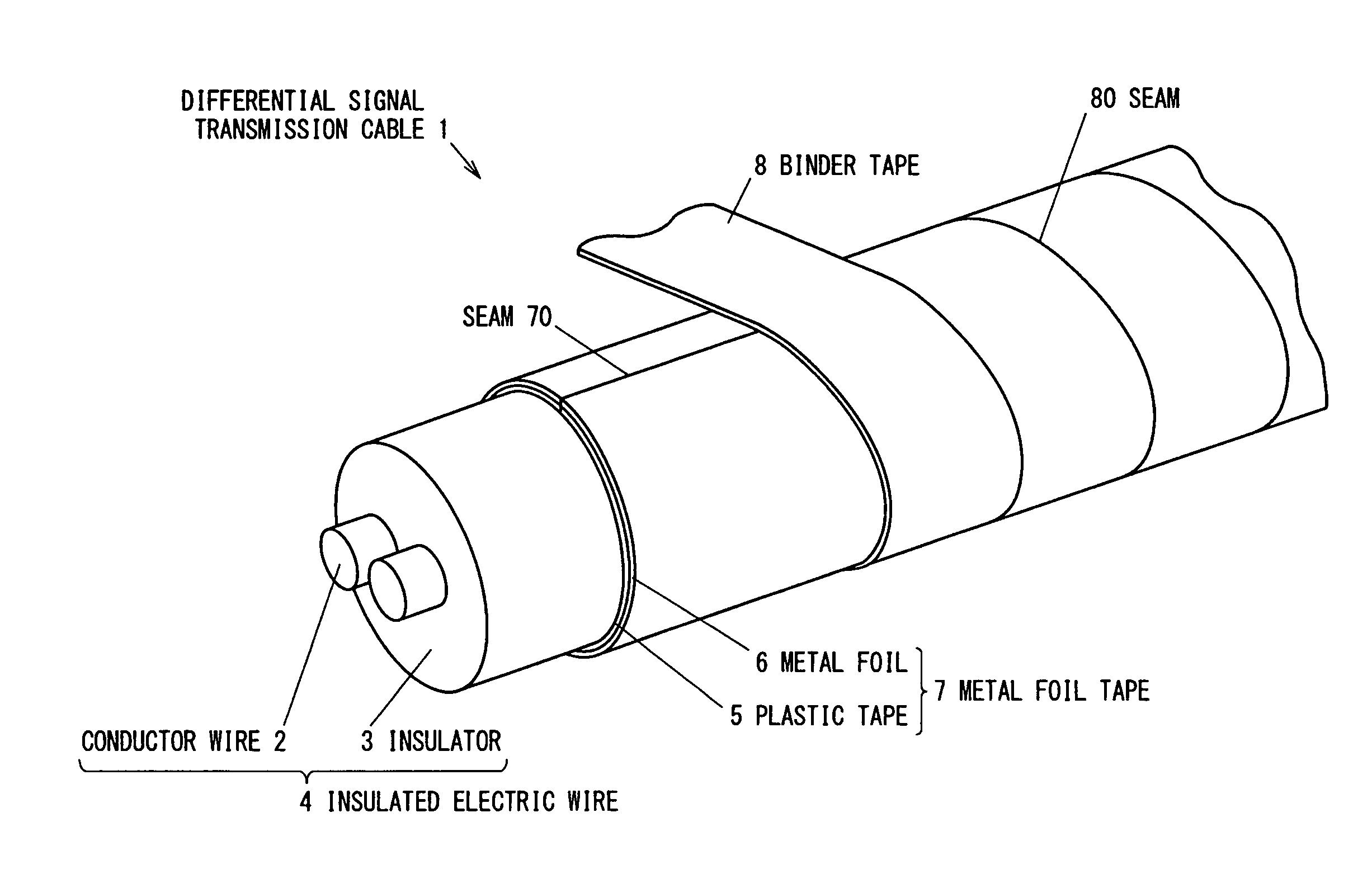
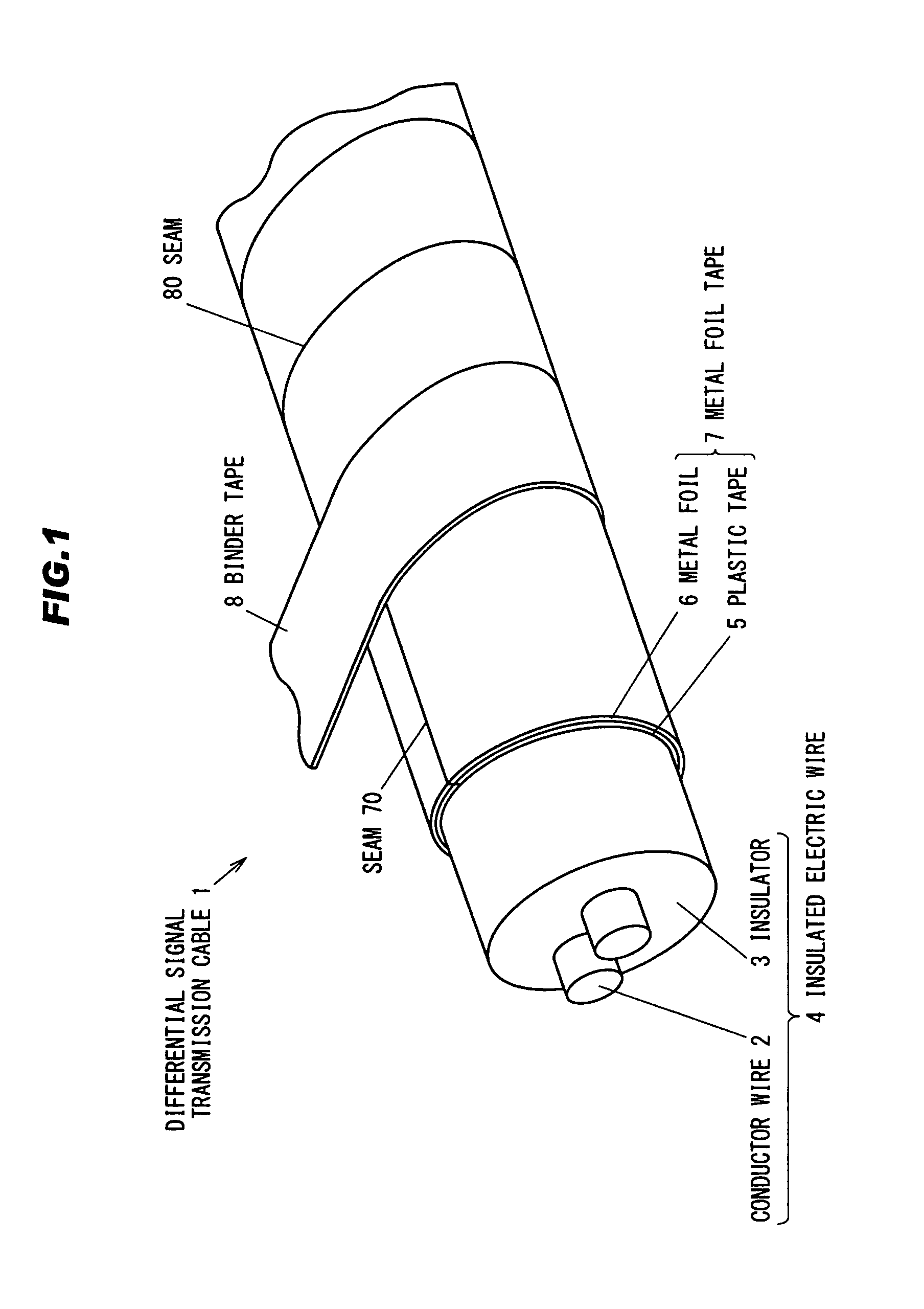
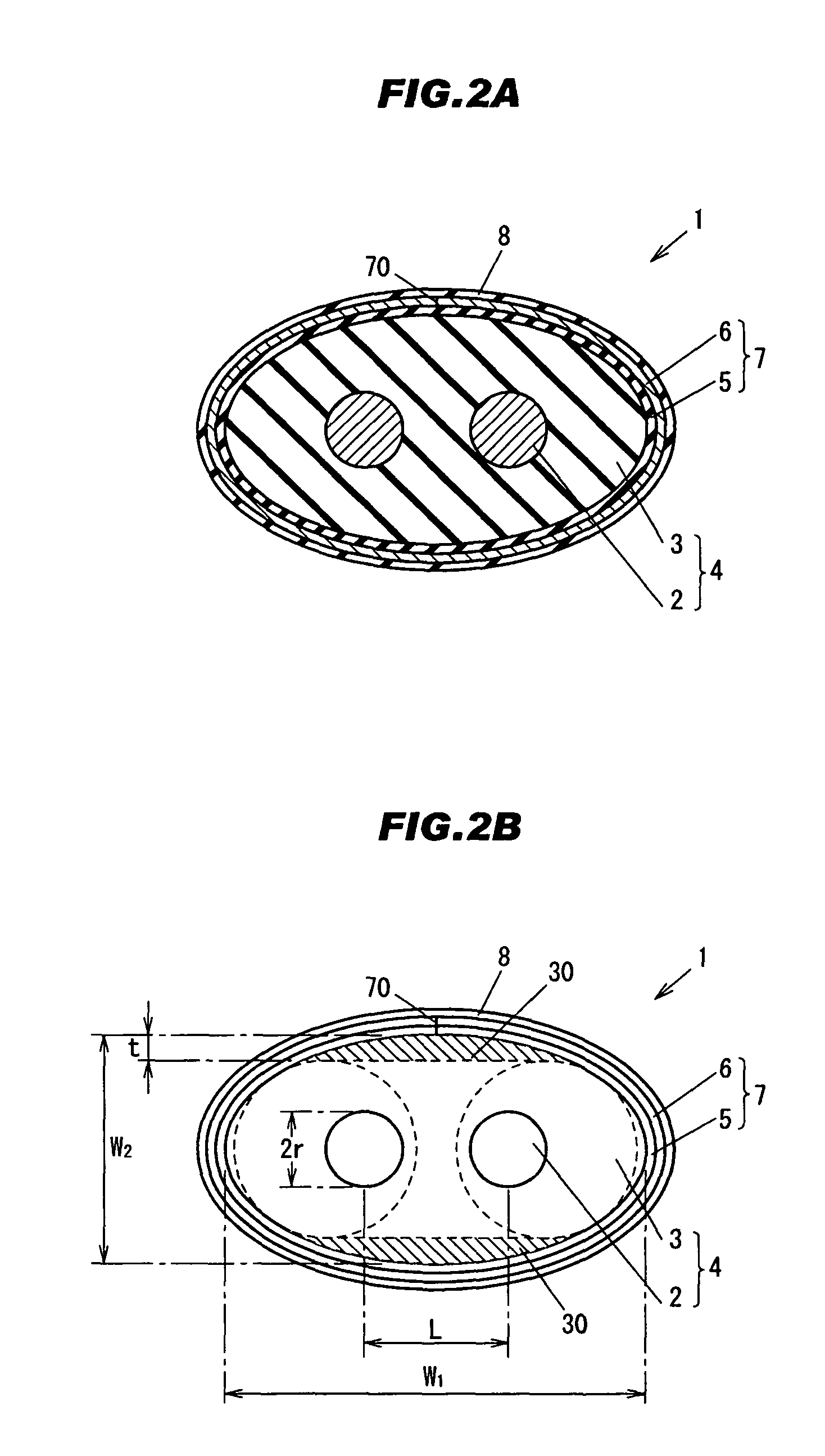
[0033]FIG. 1 is a perspective view of a differential signal transmission cable 1 in the first embodiment. FIG. 2A is a cross sectional view of the differential signal transmission cable taken along a transverse direction. FIG. 2B is a schematic diagram of a cross section of the differential signal transmission cable 1 cut along the transverse direction. In FIG. 2B, two circles indicated by dotted lines are shown for the descriptive purpose. The two circles illustrate transversal cross sectional shape of insulated electric wires to be used for making a cable having a transversal cross section similar to the differential signal transmission cable 1. In the following description, each cross section shows a cross section cut along the transverse direction unless described otherwise.
[0034]The differential signal transmission cable 1 is e.g. a cable for transmitting differential signals between or within electroni...
second embodiment
[0085]A differential signal transmission cable in the second embodiment is similar to that in first embodiment except that an outer periphery shape of a transversal cross section of the insulator 3 is elliptical.
[0086]FIG. 5A is a cross section view in a transverse direction of a differential signal transmission cable 1 in the second embodiment. FIG. 5B is graph showing a maximum value and a minimum value of the curvature radius of an outer periphery of an elliptical cross section of the insulator 3. In FIG. 5B, a horizontal axis shows an x-axis and a vertical axis shows a y-axis of the elliptical cross section of the insulator 3. In this elliptic, a major axis is on the x-axis and a minor axis is on the y-axis. In following embodiments, the same reference numerals as those in the first embodiment are used for indicating elements having the same structure and function as those in the first embodiment, and the description thereof is omitted.
[0087]In the differential signal transmissi...
third embodiment
The Third Embodiment
[0097]A differential signal transmission cable in the third embodiment is similar to that in the first and second embodiments except that a foaming degree of an inner portion of the insulator 3 is different from that of an outer periphery portion of the insulator 3.
[0098]FIG. 6 is a cross sectional view in a transverse direction of a differential signal transmission cable 1 in the third embodiment. In FIG. 6, a region surrounded by an outer periphery and a dotted line of the insulator 3 is an insulative layer 31.
[0099]In the differential signal transmission cable 1 in the third embodiment, the foaming degree of the inner portion and the foaming degree of the outer periphery portion are different from each other. As to other structure, the differential signal transmission cable 1 in the third embodiment is similar to the differential signal transmission cable 1 in the first embodiment. For example, the foaming degree of the inner portion (i.e. a portion of the ins...
PUM
| Property | Measurement | Unit |
|---|---|---|
| dielectric constant | aaaaa | aaaaa |
| width W2 | aaaaa | aaaaa |
| width W2 | aaaaa | aaaaa |
Abstract
Description
Claims
Application Information
 - R&D
- Intellectual Property
- Life Sciences
- Materials
- Tech Scout
- Unparalleled Data Quality
- Higher Quality Content
- 60% Fewer Hallucinations
Browse by: Latest US Patents, China's latest patents, Technical Efficacy Thesaurus, Application Domain, Technology Topic, Popular Technical Reports.
© 2025 PatSnap. All rights reserved.Legal|Privacy policy|Modern Slavery Act Transparency Statement|Sitemap|About US| Contact US: help@patsnap.com


