Differential signal transmission cable

Active Publication Date: 2012-07-26
HITACHI METALS LTD
View PDF8 Cites 37 Cited by
  • Summary
  • Abstract
  • Description
  • Claims
  • Application Information

AI Technical Summary

Benefits of technology

[0021]According to the differential signal transmission cable of the present invention, it

Problems solved by technology

As a result, there is a slack in the metal foil tape, i.e. the metal foil tape tends to be released.
In the conventional parallel twin-core shielded electri

Method used


Image

  • Differential signal transmission cable
  • Differential signal transmission cable
  • Differential signal transmission cable

Examples


first embodiment

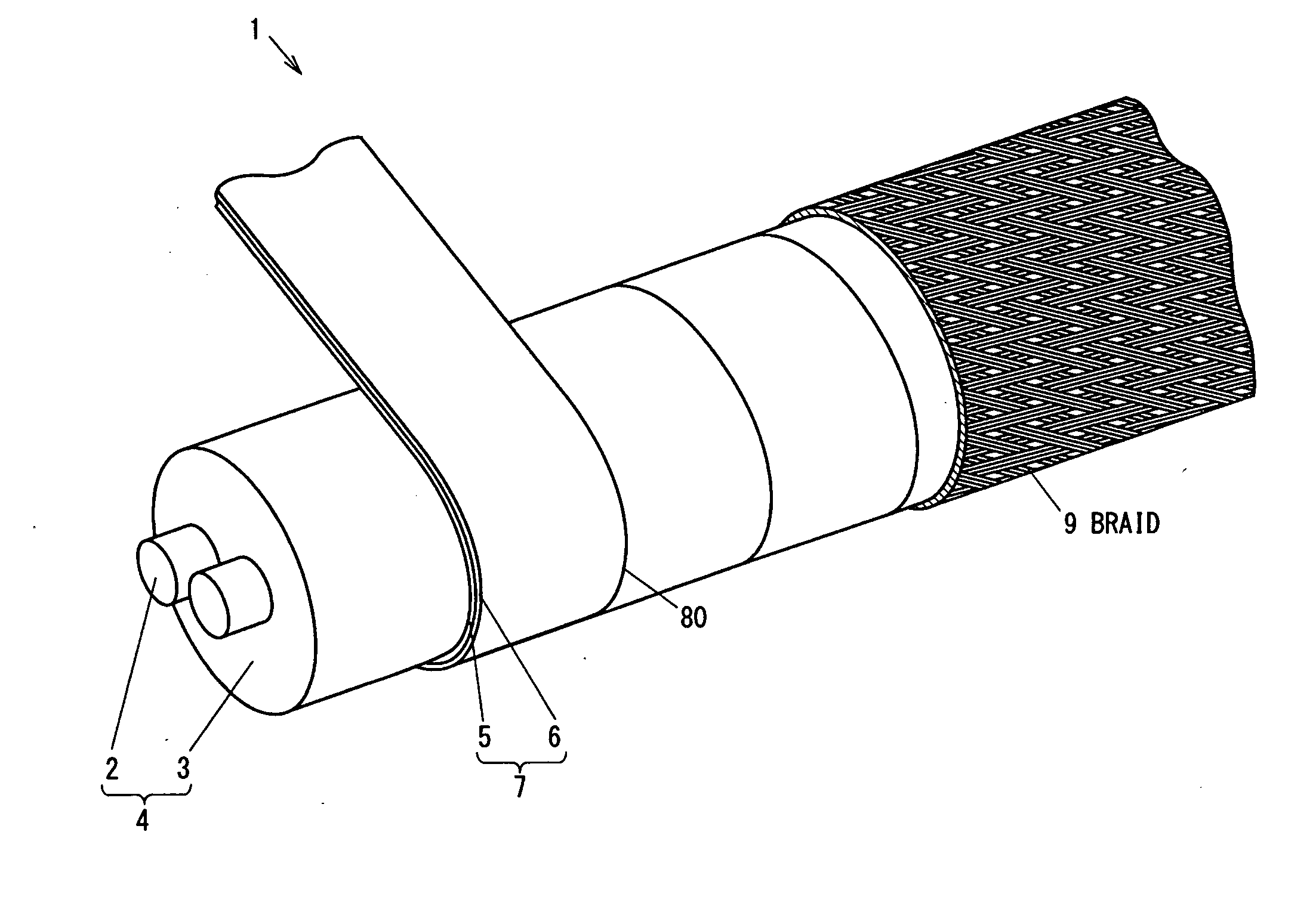
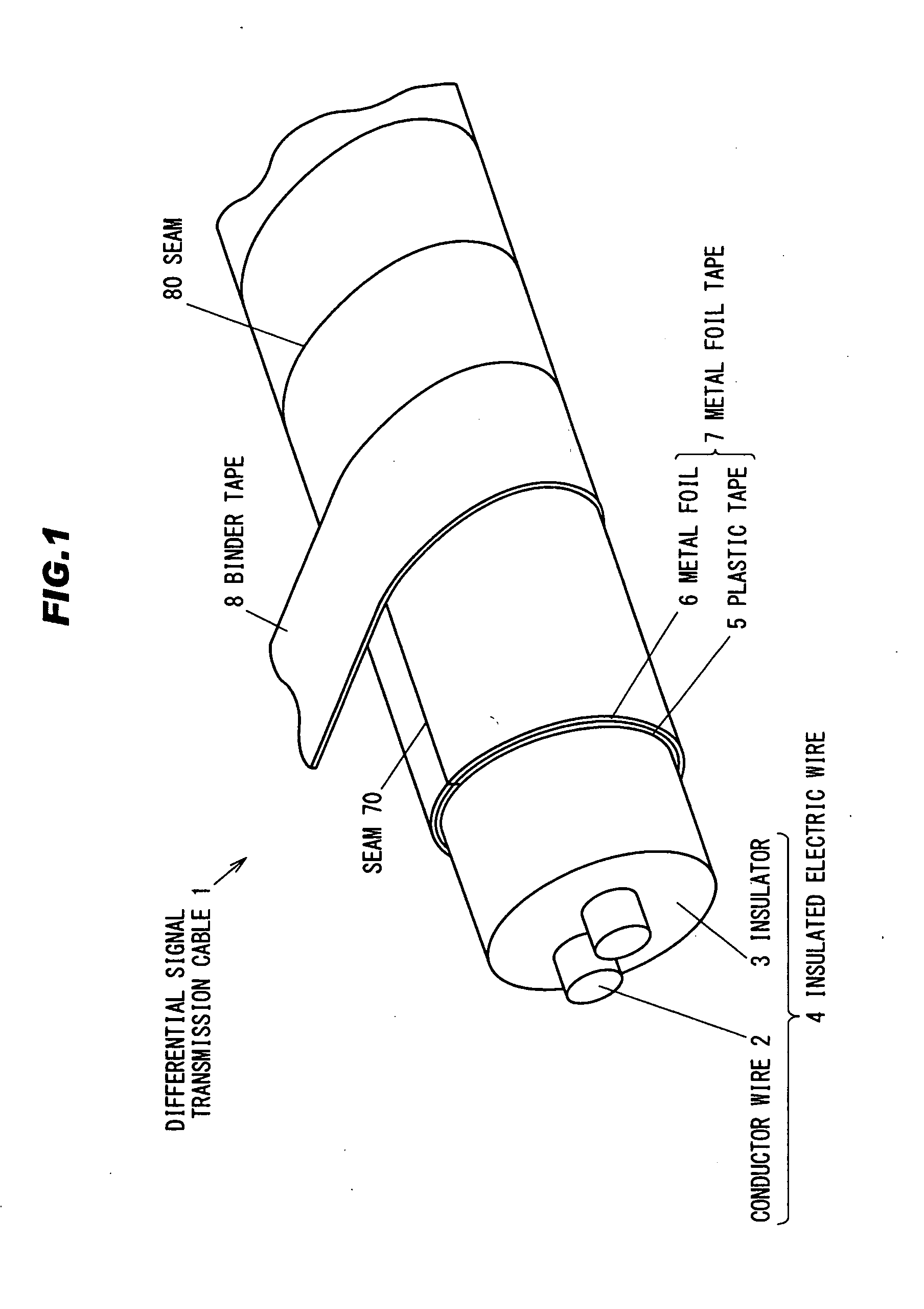
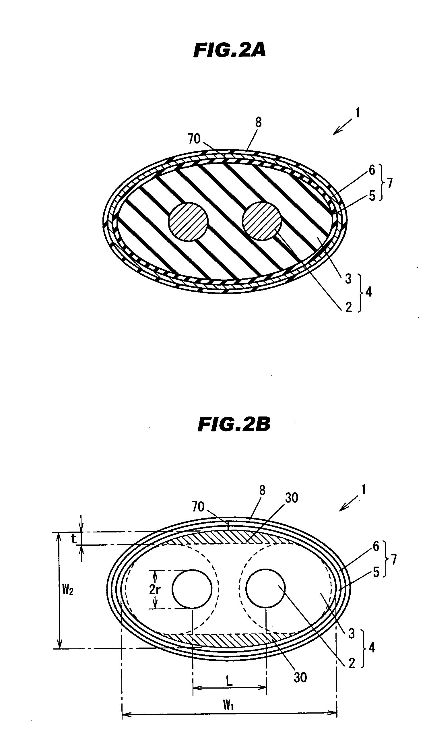
[0032](Outline of a Structure of a Differential Signal Transmission Cable 1)

[0033]FIG. 1 is a perspective view of a differential signal transmission cable 1 in the first embodiment. FIG. 2A is a cross sectional view of the differential signal transmission cable taken along a transverse direction. FIG. 2B is a schematic diagram of a cross section of the differential signal transmission cable 1 cut along the transverse direction. In FIG. 2B, two circles indicated by dotted lines are shown for the descriptive purpose. The two circles illustrate transversal cross sectional shape of insulated electric wires to be used for making a cable having a transversal cross section similar to the differential signal transmission cable 1. In the following description, each cross section shows a cross section cut along the transverse direction unless described otherwise.

[0034]The differential signal transmission cable 1 is e.g. a cable for transmitting differential signals between or within electroni...

second embodiment

[0084]A differential signal transmission cable in the second embodiment is similar to that in first embodiment except that an outer periphery shape of a transversal cross section of the insulator 3 is elliptical.

[0085]FIG. 5A is a cross section view in a transverse direction of a differential signal transmission cable 1 in the second embodiment. FIG. 5B is graph showing a maximum value and a minimum value of the curvature radius of an outer periphery of an elliptical cross section of the insulator 3. In FIG. 5B, a horizontal axis shows an x-axis and a vertical axis shows a y- axis of the elliptical cross section of the insulator 3. In this elliptic, a major axis is on the x-axis and a minor axis is on the y-axis. In following embodiments, the same reference numerals as those in the first embodiment are used for indicating elements having the same structure and function as those in the first embodiment, and the description thereof is omitted.

[0086]In the differential signal transmiss...

third embodiment

The Third Embodiment

[0095]A differential signal transmission cable in the third embodiment is similar to that in the first and second embodiments except that a foaming degree of an inner portion of the insulator 3 is different from that of an outer periphery portion of the insulator 3.

[0096]FIG. 6 is a cross sectional view in a transverse direction of a differential signal transmission cable 1 in the third embodiment. In FIG. 6, a region surrounded by an outer periphery and a dotted line of the insulator 3 is an insulative layer 31.

[0097]In the differential signal transmission cable 1 in the third embodiment, the foaming degree of the inner portion and the foaming degree of the outer periphery portion are different from each other. As to other structure, the differential signal transmission cable 1 in the third embodiment is similar to the differential signal transmission cable 1 in the first embodiment. For example, the foaming degree of the inner portion (i.e. a portion of the ins...


PUM


Abstract

A differential signal transmission cable has a pair of conductors arranged to be distant from each other and parallel to each other, an insulator covering the pair of conductors, and a shield conductor wound around the insulator. The insulator has an outer periphery shape of a transversal cross section in that a plurality of curved lines with different curvature radiuses are combined. The shield conductor has an inner periphery shape of a transversal cross section in that the plurality of curved lines are combined in accordance with the outer periphery shape of the insulator.

Description

[0001]The present application is based on Japanese patent application No. 2011-011708 filed on January 24, 2011 and Japanese patent application No. 2011-196737 filed on Sep. 9, 2011, the entire contents of which are incorporated herein by reference.BACKGROUND OF THE INVENTION[0002]1. Field of the Invention[0003]The present invention relates to a differential signal transmission cable.[0004]2. Description of the Related Art[0005]As one example of conventional differential signal transmission cables, Japanese Patent Laid-Open No. 2002-289047 (JP-A 2002-289047) discloses a parallel twin-core shielded electric wire, in which a pair of insulated electric wires are arranged in parallel, at least one drain conductor is arranged in parallel with the insulated electric wires, the pair of insulated electric wires and the drain conductor are wound up collectively with a metal foil tape as a shield conductor, and an outer periphery part of this shield conductor is covered with a jacket.[0006]Ac...

Claims


Application Information

Patent Timeline
IPC IPC(8): H01B11/06
CPCH01B11/1834H01B11/20H01B7/17H01B11/002
Inventor SUGIYAMA, TAKAHIRONONEN, HIDEKIKUMAKURA, TAKASHI
Owner HITACHI METALS LTD
Why Eureka
Try Eureka