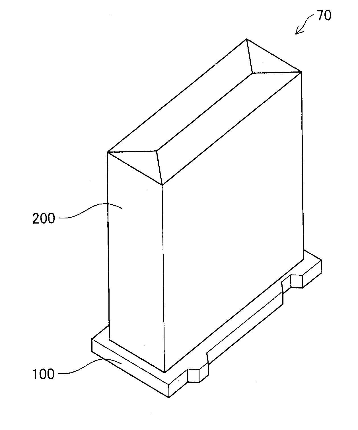
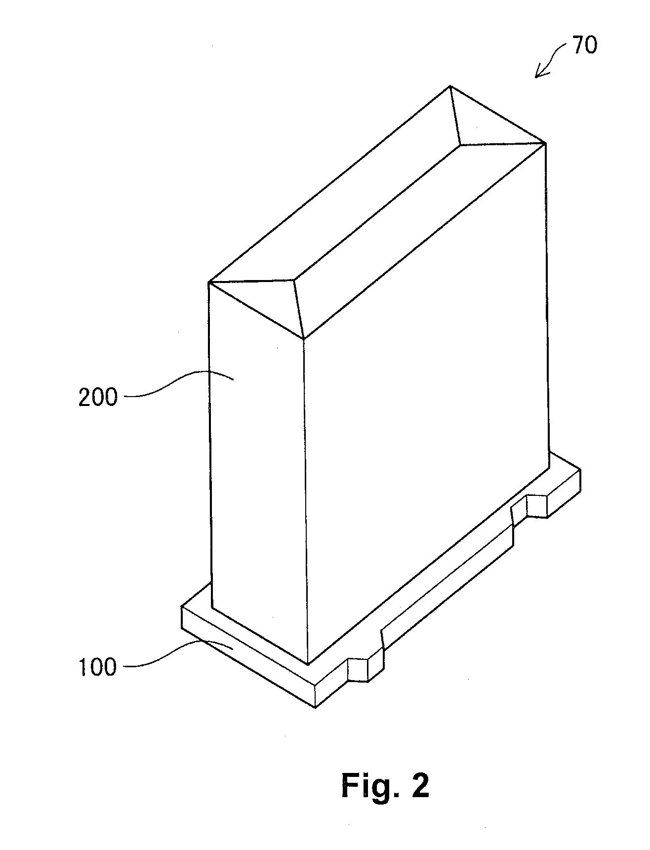
Liquid container

a technology for liquid containers and containers, applied in the field of liquid containers, can solve the problems of increasing the risk of miswriting, and achieve the effect of improving the reading and writing precision of the information recording unit and good precision

Active Publication Date: 2014-02-25
SEIKO EPSON CORP
View PDF26 Cites 0 Cited by
  • Summary
  • Abstract
  • Description
  • Claims
  • Application Information

AI Technical Summary

Benefits of technology

[0013]With this liquid container, the container section enclosing the liquid containing space capable of containing liquid is formed using a plant derived material, so it is possible to reduce the environmental burden of the liquid container during its life cycle. Also, with this liquid container, the information recording unit is provided above the high rigidity member which contains a material different from the material of the first container section and also has higher rigidity than the first container section. By doing this, skewing of the relative positional relationship of the reading means or writing means provided on the liquid consuming apparatus and the information recording unit is suppressed. As a result, it is possible to achieve an improvement in the precision when reading the information recording unit using the reading means or writing to the information recording unit using the writing means (suppressing the occurrence of misreading or miswriting).
[0033]With this liquid container, it is possible to align the liquid container with the liquid container holder with good precision while achieving an improvement in the reading and writing precision of the information recording unit.

Problems solved by technology

Here, such problems are in common with a liquid container which is adapted to be mounted in a liquid container holder of a liquid consuming apparatus without being limited to ink cartridges which are mounted in a holder of an ink jet printer.
When the information is written in a state with the writing means in contact with the information recording unit, the risk of miswriting increases.

Method used


Image

  • Liquid container
  • Liquid container
  • Liquid container

Examples


first working example

A. FIRST WORKING EXAMPLE

[0067]A-1. Printer Configuration

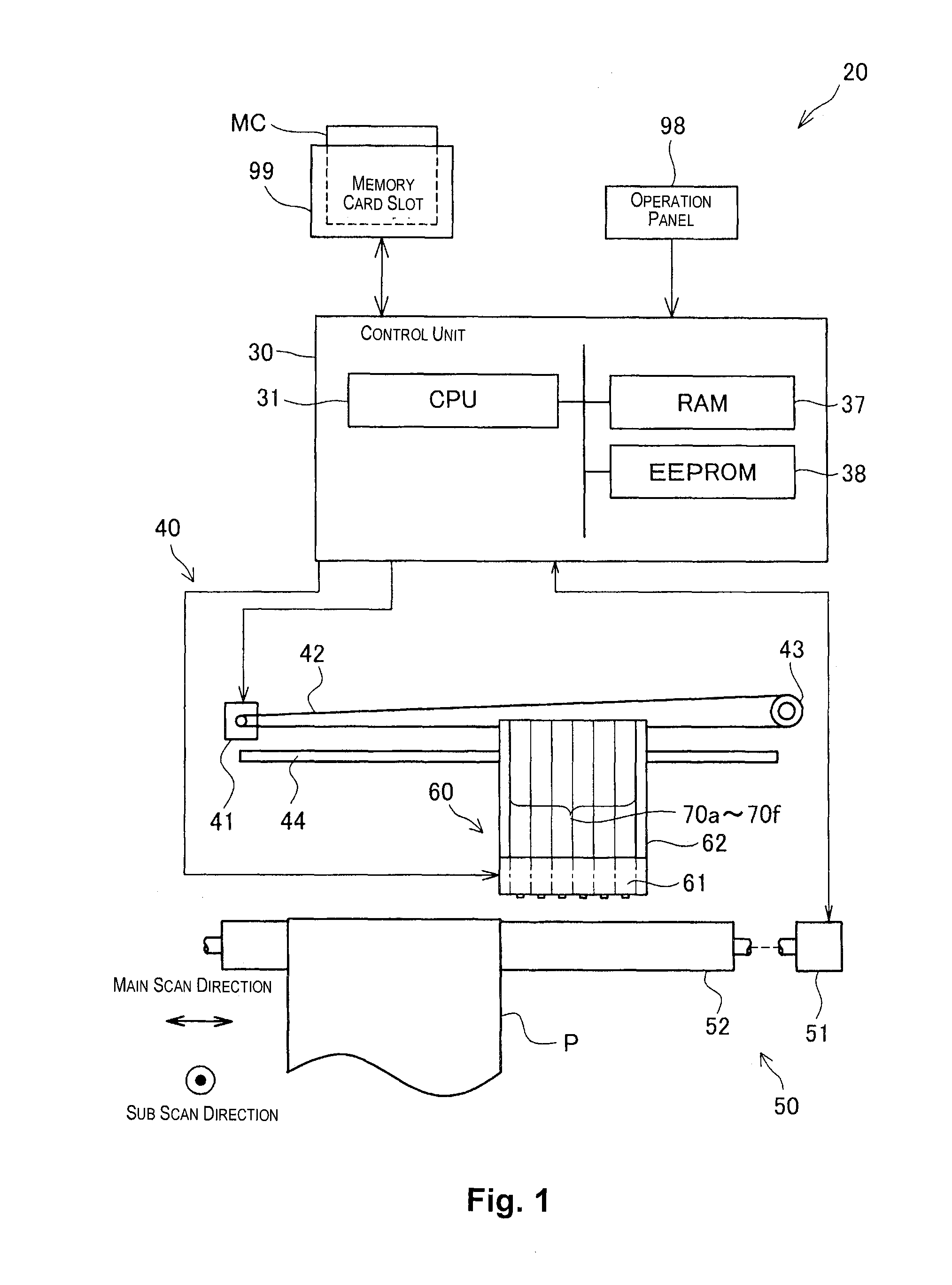
[0068]FIG. 1 is an explanatory diagram illustrating the schematic configuration of the printer 20 of the first working example. The printer 20 in the present working example is an ink jet printer which forms ink dots on a print medium by ejecting ink from a plurality of nozzles, and thereby records characters, graphics, images or the like on the print medium. The printer 20 is one liquid consuming apparatus which consumes ink as a liquid.

[0069]As shown in FIG. 1, the printer 20 is provided with a print head unit 60 on which a print head 61 is mounted, a print head unit transport mechanism 40 which performs main scanning in which the print head unit 60 is moved back and forth along a direction which is parallel to a shaft of a platen 52, a paper transport mechanism 50 which performs sub-scanning in which a paper sheet P as a print medium is transported in a direction (sub-scanning direction) which intersects with the main scanni...

first working example modified example

A-3. FIRST WORKING EXAMPLE MODIFIED EXAMPLE

[0092]FIG. 12 is an explanatory diagram illustrating a modified example of a configuration for fixing the containing box 200 and the flow path member 100. The modified example shown in FIG. 12 differs from the first working example shown in FIG. 9 in that the protruding section 120 is movable. Specifically, with the modified example shown in FIG. 12, in the state before the containing box 200 is fixed, the protruding section 120 of the flow path member 100 is in a state substantially parallel with the base section 110, and at the boundary position of the protruding section 120 and the base section 110, for example, a hinge part 128 for which the thickness is made thinner and the rigidity is reduced is formed. By arranging the containing box 200 at the position at which it is to be fixed, and bending the protruding section 120 at substantially a 90 degree angle with the hinge part 128 as a fulcrum, a state is formed in which the protruding s...

second working example

B. SECOND WORKING EXAMPLE

B-1. Printer Configuration:

[0095]FIG. 15 is an explanatory diagram illustrating a schematic configuration of the printer 20 of the second working example. The printer 20 of the second working example differs from the printer 20 of the first working example shown in FIG. 1 mainly in that it is equipped with a reading unit 80 and a writing unit 90, and also in that the ink cartridge 70 has a label 180 on which information relating to the ink cartridge 70 is recorded (a detailed description is given later).

[0096]The reading unit 80 reads information recorded on the label 180 of the ink cartridge 70, and the writing unit 90 writes (records) information to the label 180 of the ink cartridge 70. With this working example, the reading unit 80 and the writing unit 90 are installed in a fixed manner above the print head unit 70 along the gravitational direction.

[0097]The arrangement of the reading unit 80 and the writing unit 90 along the main scan direction is an ar...


PUM


Abstract

The environmental burden of a liquid container during its life cycle is reduced, and a decrease in the reading or writing precision of an information recording unit provided on the liquid container is suppressed. A liquid container mounted in a liquid container holder of a liquid consuming apparatus, equipped with a first container section enclosing at least a portion of a liquid containing space capable of containing a liquid, the material thereof including a plant derived material, a high rigidity member having higher rigidity than the first container section, the material thereof including a material different from the plant derived material, and an information recording unit positioned above the high rigidity member, in which information relating to the liquid container is recorded, for which the information is read or written by a reading unit or a writing unit provided on the liquid consuming apparatus.

Description

CROSS-REFERENCE TO RELATED APPLICATION[0001]This application claims priority on the basis of Japanese Patent Application No. 2011-275914 filed on Dec. 16, 2011, and this application is incorporated in this specification by reference.BACKGROUND[0002]1. Technical Field[0003]The present invention relates to a liquid container where it is possible for a liquid to be contained.[0004]2. Related Art[0005]Ink jet printers, which record images or text by ejecting ink onto a print medium from a plurality of nozzles which are provided in a print head, are widely used. In the ink jet printers, an ink cartridge containing ink is mounted in a holder and ink is supplied to the print head from the ink cartridge.[0006]In the life cycle from the manufacturing to the disposal of the ink cartridge, it is desirable to reduce the burden on the environment as much as possible. In the past, there have been known ink cartridges with a configuration in which an ink pack which is formed by a thermoplastic fil...

Claims


Application Information

Patent Timeline
Patent Type & Authority Patents(United States)
IPC IPC(8): B41J2/175
CPCB41J2/17559B41J2/17513B41J2/17553B41J2/17506B41J2/17546B65D85/00B41J2/1752B41J2/17533
Inventor MATSUMOTO, AKIHITO
Owner SEIKO EPSON CORP
Why Eureka
Try Eureka