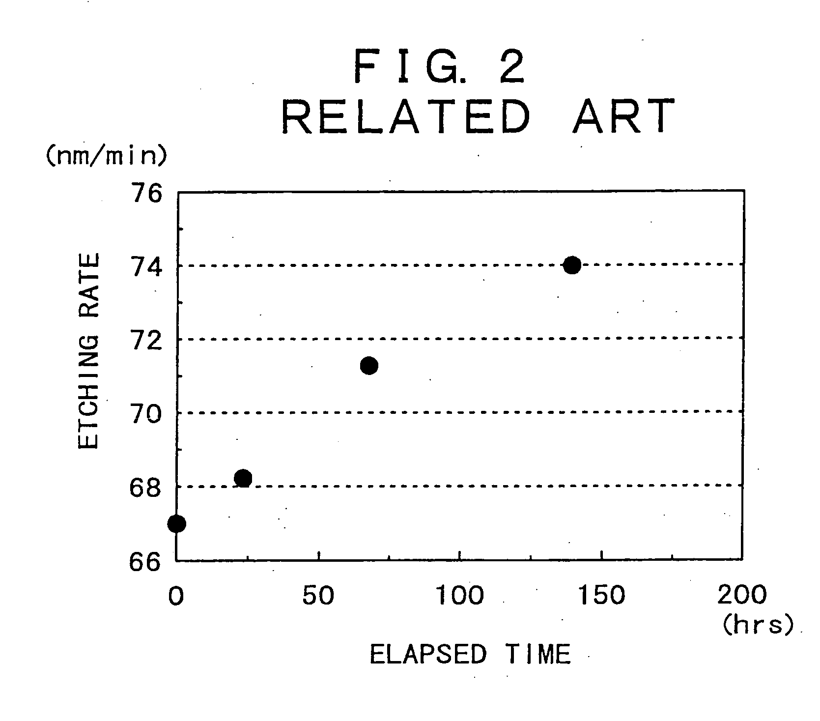
In consequence, the cleaning process in the above related art is of no effect on uniform and stable cleaning by reason of the considerably non-uniform change in concentration rise as well as the increase in
etching rate of the
silicon oxide or the glass
substrate surface layer with the lapse of time as shown in FIG. 2, resulting in problems inclusive of difficulty in providing higher yield of the
semiconductor substrate and the
liquid crystal display substrate.
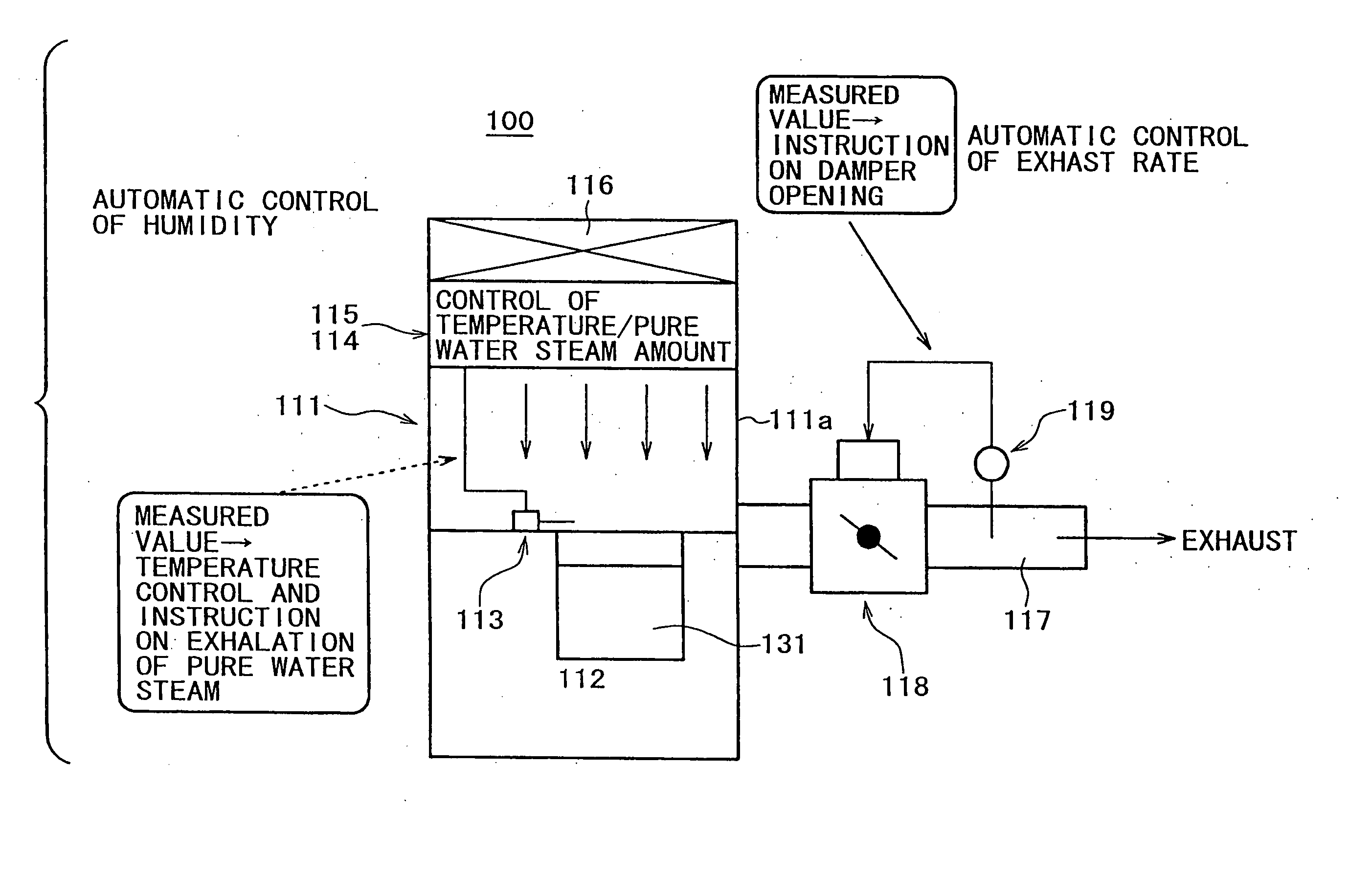
That is, one of the causes is that a
water content exhaled from the cleaning solution is discharged to the outside of the cleaning draft together with clean air.
However, a considerably large amount of cleaning solution is required for performing the above measure.
However, the waste fluid treatment in this case brings about not only the need for a large amount of resources consumed, that is, waste
water treatment agents but also the increase in released waste (waste water and
sludge) amount with the increasing amount of resources consumed, as is apparent from a
material balance view of FIG. 4.
Incidentally, the global environmental issues have been recently made as a matter of worldwide concerns, and influences of the
semiconductor or LCD substrate manufacture process on the environment have been at issue.
However, this cleaning apparatus, although uses a humidified air curtain, has difficulty in maintaining the cleanliness of substrates to be cleaned by reason of the horizontal flow of clean air, and besides, needs to discontinue the flow of air every operation of taking in and out the substrates to be cleaned, resulting in problems inclusive of the need for troublesome operations.
As described above, the substrate wet-cleaning process in the related art is also of no effect on uniform and stable cleaning by reason of the considerably non-uniform change in concentration rise as well as the increase in
etching rate of the
silicon oxide layer (or the glass
substrate surface) with the lapse of cleaning time (that is, with the elapsed time since it started to use the cleaning solution for the cleaning process), resulting in problems inclusive of difficulty in providing higher yield of the
semiconductor substrate and the
liquid crystal display substrate.
That is, one of the causes is that a
water content is exhaled from the cleaning solution.
However, a considerably large amount of cleaning solution is required for the above means.
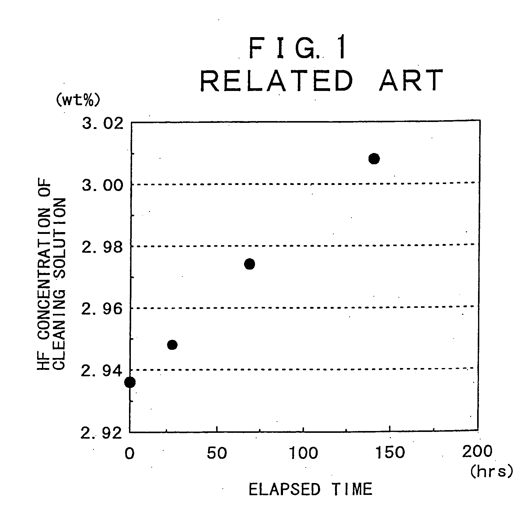
The above problem is caused by the
gradual increase in concentration of hydrofluoric acid component in the cleaning solution with the lapse of time in the process of being used.
However, a considerably large amount of cleaning solution is required for the above measure (In particular, since the
ammonium fluoride cleaning solution is used at the concentration as high as several ten wt.
), resulting in the increase in
ammonium fluoride or hydrofluoric acid consumption (chemical cost) with the increasing amount of cleaning solution used.
However, the waste
water treatment in this case brings about not only the need for a large amount of resources (waste
water treatment agents) consumed but also the increase in released waste (waste water and
sludge) amount with the increasing amount of resources consumed (See FIG. 4).
Incidentally, the global environmental issues have been recently made as a matter of worldwide concerns, and the environmental burden on the semiconductor or LCD substrate manufacture process has been at issue.

