Well control method for changing valve under pressure

A technology for changing valves and valves under pressure, which is applied in the valve device of wellbore/well, earthwork drilling, wellbore/well components, etc. The effect of the simple structure of the device

Inactive Publication Date: 2008-02-06
广汉川油井控装备有限公司
View PDF0 Cites 20 Cited by
  • Summary
  • Abstract
  • Description
  • Claims
  • Application Information

AI Technical Summary

Problems solved by technology

[0005] The purpose of the present invention is to solve the problems in the prior art that it is not easy to replace the damaged valves of oil and gas field wellhead equipment or the replacement process is time-consuming, laborious, and costly in property. Under normal circumstances, the damaged valves can be removed under pressure under well control, especially the valves directly connected to the tubing can be replaced. The advantages

Method used


Image

  • Well control method for changing valve under pressure
  • Well control method for changing valve under pressure
  • Well control method for changing valve under pressure

Examples


Embodiment Construction

[0058] The present invention will be further described below in combination with specific embodiments and accompanying drawings.

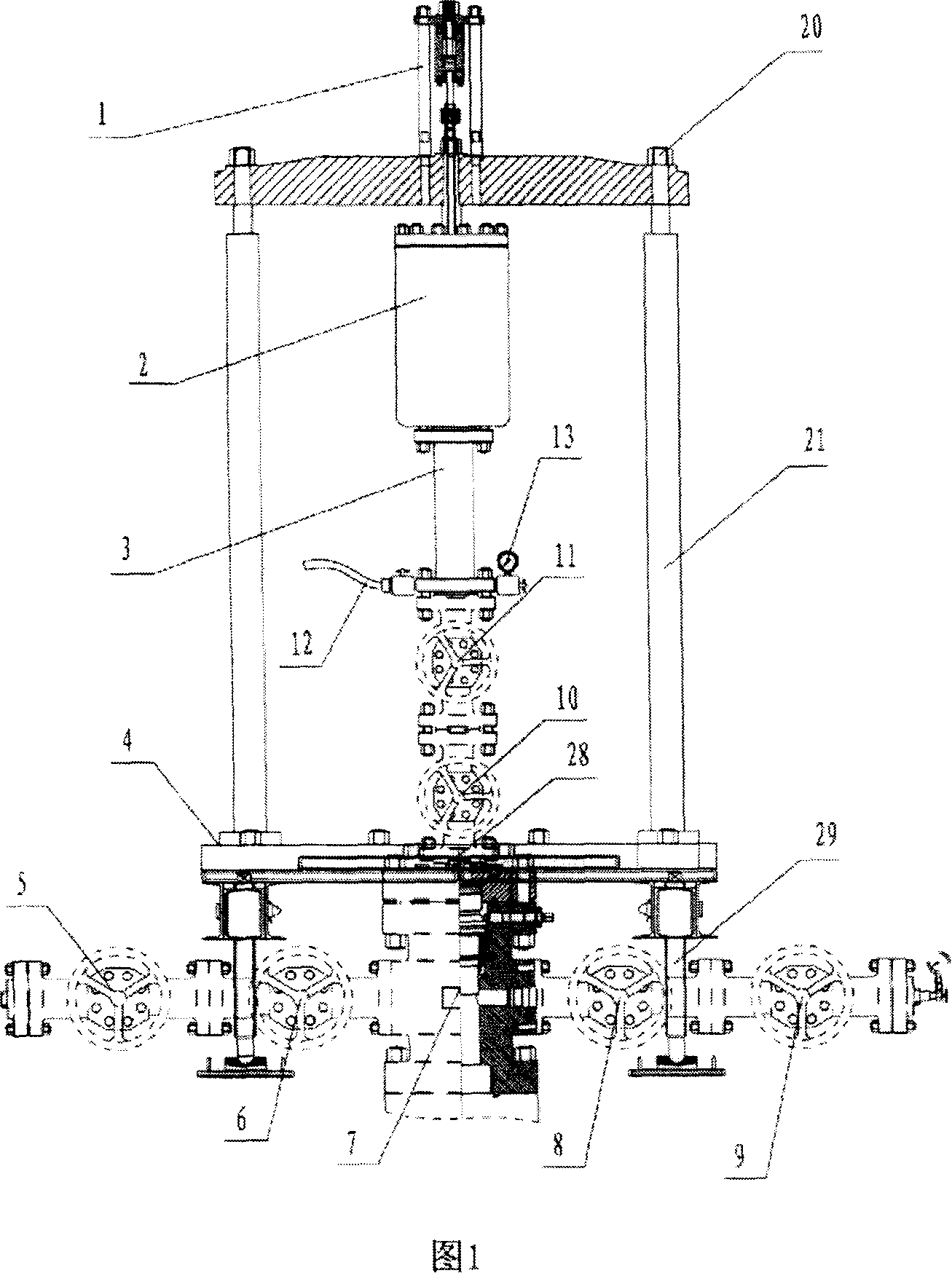
[0059] First of all, the special device structure required by the present invention will be described. As shown in Figure 1, the device includes a plug assembly 1, a lifting hydraulic support 21, a self-sealing head assembly 2, a double flange pup joint assembly 3, an underframe assembly 4 that can be arranged on the tubing jacket 7, and Hydraulic control system.

[0060] The underframe assembly 4 includes several support screw rods 29 arranged around the tubing jacket 7, and a support plate arranged on the upper end of the support screw rod 29 and connected thereto. A small pressure plate 30 is arranged on the top, and the edge of the support plate is provided with an adjusting bolt passing through the small pressure plate 30 , and the middle part of the small pressure plate 30 is provided with a perforation with an adjustable aperture.

[0061]...


PUM


Abstract

The present invention relates to a method of replacing a valve by a well-controlled pressure, and belongs to the method of oil and gas field wellhead practices. The present invention is aimed at resolving the problems that the damaged valves of the oil and gas field wellhead equipment are not replaced easily or the process of the replacement in the prior art is time-consuming, laborious and costly; the operational steps are like that: an under bed assembly is positioned over the end of the oil pipe; a lifting bracket which can move upwards and downwards is arranged at the under bed assembly;. a blanking plug assembly with a lifting pole which can move upwards and downwards is arranged on the lifting bracket; And a self-sealed head assembly and a double-flange short section assembly which can be pressed are covered outside the lifting pole; the lifting pole first extends downwards into an oil pipe loop and then lifts upwards, so that the sealing ring covered outside the lower part of the lifting pole is expanded to block the inner diameter of the oil pipe loop; the damaged valve can be disassembled and taken out from the top end of the lifting pole, and then a new valve can be positioned at the oil pipe loop from the top end of the lifting pole; and after the finish of the equipment of the new valve, the elements mentioned above can be disassembled, and the replacing valve practice by well-controlled pressure is finished. The present invention can be used in the replacing valve by well-controlled pressure in oil and gas field wellhead practices.

Description

technical field [0001] The invention belongs to a wellhead operation method of an oil and gas field, in particular to a method for implementing well control, disassembly, assembly and replacement of valves in a pressurized state. Background technique [0002] During the long-term use of oil and gas trees in the petroleum industry, due to the quality and performance of the equipment and the aging of the seals, as well as the H in the well fluid 2 S and CO 2 Corrosive substances will increase the corrosion and wear of the valve, resulting in leakage of the valve. The long-term wear and tear of the screw and nut of the valve may cause damage. In this case, the valve must be replaced (overhauled). [0003] In the past few decades, the oil and gas fields used to install the derrick and a series of auxiliary facilities for the valve replacement operation after the main valve of the oil (gas) tree was damaged. The previous set of drilling equipment adopts the method of killing th...

Claims


Application Information

Patent Timeline
Patent Type & Authority Applications(China)
IPC IPC(8): E21B23/00E21B34/02
Inventor 黄勇秦世宽王伸龙严永发
Owner 广汉川油井控装备有限公司
Why Eureka
Try Eureka