Braided wire machining apparatus and method for manufacturing end extended braided wire

A processing device and braided wire technology, which is applied in the direction of cable/conductor manufacturing, electrical components, circuits, etc., can solve the problems of scattered and uneven multiple busbars, marshalling shielding wires and poor installation of shielding shells, etc., to prevent scattered, The effect of suppressing skew

Inactive Publication Date: 2013-05-29
SUMITOMO WIRING SYST LTD
View PDF1 Cites 0 Cited by
  • Summary
  • Abstract
  • Description
  • Claims
  • Application Information

AI Technical Summary

Problems solved by technology

Therefore, it is easy to cause poor installation between the braided shielded wire and the shielded case
[0006] Especially in the case of using thinner diameter braided shielded wires due to requirements such as cost reduction, since the ends of the braided wires need to be greatly expanded, the busbars at the ends become sparse and have lower stiffness, which is easy A state where multiple busbars are scattered and not neat

Method used


Image

  • Braided wire machining apparatus and method for manufacturing end extended braided wire
  • Braided wire machining apparatus and method for manufacturing end extended braided wire
  • Braided wire machining apparatus and method for manufacturing end extended braided wire

Examples


Embodiment Construction

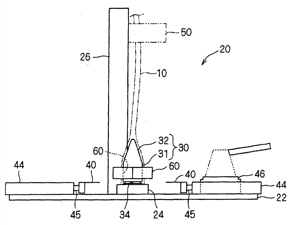
[0046] Next, a braided yarn processing device according to an embodiment will be described.

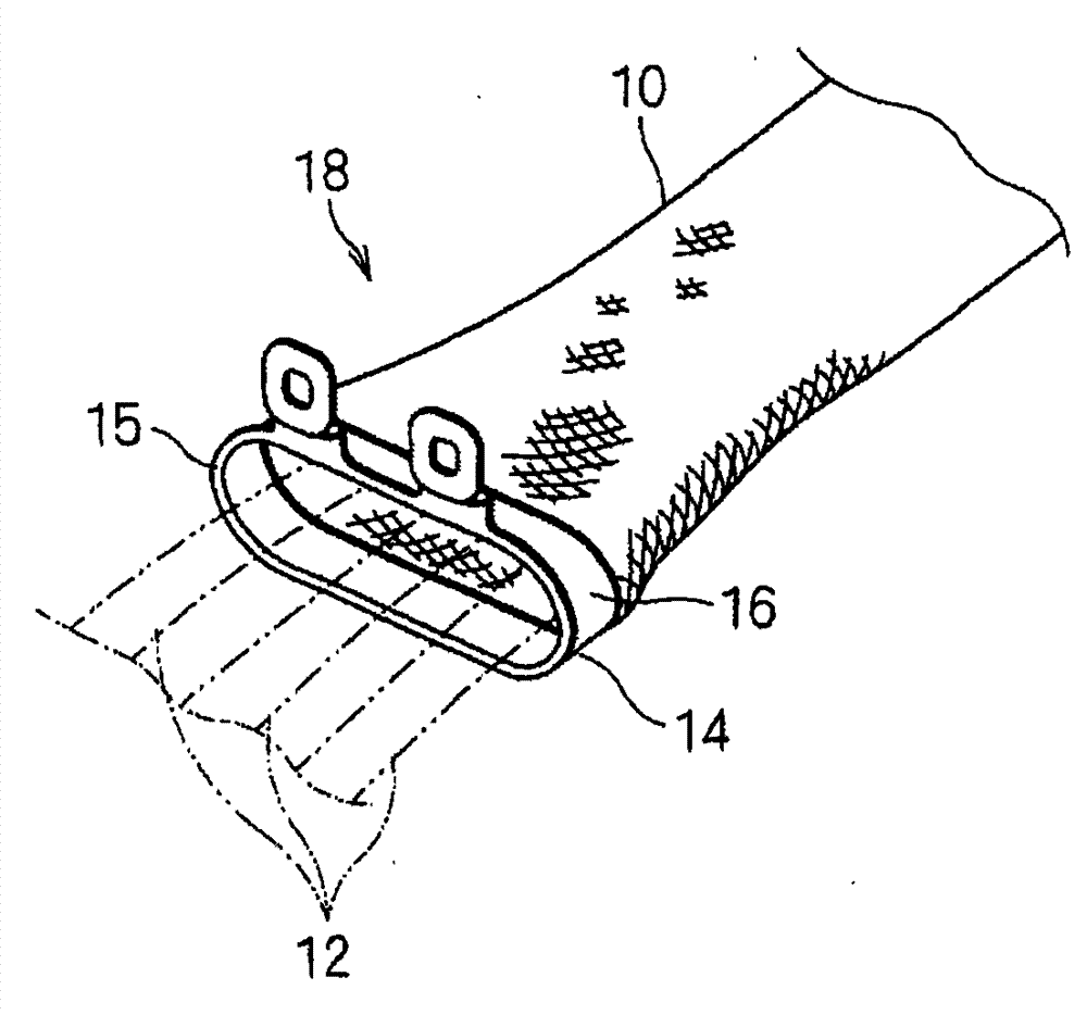
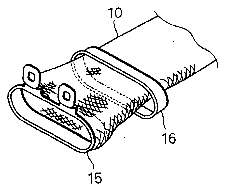
[0047] First, the braided yarn to be processed will be described. figure 1 It is a schematic perspective view showing an example of a shielded wire harness 18 using a braided wire 10, figure 2 It is an explanatory diagram showing one manufacturing process of the shielded wire harness 18 .

[0048] The shielded wire harness 18 is a wiring member applied to electric vehicles such as hybrid vehicles, and has braided wires 10 , electric wires 12 and end fittings 14 . The braided wire 10 has a structure in which fine metal wires are braided to form a mesh cylinder. In addition, the thin metal wire braided to constitute the braided wire 10 may be further formed by twisting a plurality of bus wires (for example, wires with an outer diameter of 0.18 mm). The end fitting 14 has a substantially elongated cylindrical fitting body portion 15 and a crimping fitting 16 . In addition, the end o...


PUM


Abstract

The present invention provides a braided wire machining apparatus capable of forming neat state as best as one can on the end of the extended braided wire and method for manufacturing end extended braided wire. A braided wire machining apparatus (20) for the extension of the end of the braided wire (10), has a core part member (30), formed as a shape gradually enlarged from the front end side to the base terminal side, to spread the braided wire; a braided wire temporarily holding member (60), having a temporary holding hole (62) which can be embedded by axial mid portion of core part member (30), can temporarily hold and inlay the braided wire(10) of the core part member (30) between the core part member (30), by outer inlayed to the core part member (30); and a coiling piece (40), configured to be able to move towards or leave from the base terminal side external circumstance part of the core part member (30), for bending and coiling the terminal edge part of the braided wire (10 ) in outer inlay on the core part member(30) by moving toward the base terminal side external circumstance part of the core part member (30).

Description

technical field [0001] The present invention relates to a technique of expanding the end of a cylindrical braided wire. Background technique [0002] Conventionally, there is an invention disclosed in Patent Document 1 as a wire harness including a cylindrical braided wire. [0003] Patent Document 1 discloses a high-voltage wire harness for electric vehicles in which electric wires are inserted through shielded electron tubes. The structure of the shielded electron tube used here is as follows: the end of the mesh cylindrical braided shielded wire is covered on the peripheral surface of the ring-shaped shielded shell, and then the clamping ring is covered and tightened on the outer periphery of the braided shielded wire. Installed on the surrounding surface of the shielding case. [0004] Patent Document 1: (Japanese) Unexamined Patent Publication No. 2003-257264 [0005] However, in order to cover the above-mentioned braided shielded wires on the peripheral surface of t...

Claims


Application Information

Patent Timeline
Patent Type & Authority Patents(China)
IPC IPC(8): H01B13/00
Inventor 田中武彦板谷畅之
Owner SUMITOMO WIRING SYST LTD
Why Eureka
Try Eureka