Peg board display fastener and connector

a technology of fasteners and clips, applied in the direction of screws, washing machines, ways, etc., can solve the problems of clip not being convenient to remove, clip is not disposable and not suitable for reuse, and is easily ripped out of pla

a technology of fasteners and clips, applied in the direction of screws, washing machines, ways, etc., can solve the problems of clip not being convenient to remove, clip is not disposable and not suitable for reuse, and is easily ripped out of pla

US8616091B2Active Publication Date: 2013-12-31PROCESS DISPLAY LLC

Image

  • Peg board display fastener and connector
  • Peg board display fastener and connector
  • Peg board display fastener and connector

Examples


Embodiment Construction

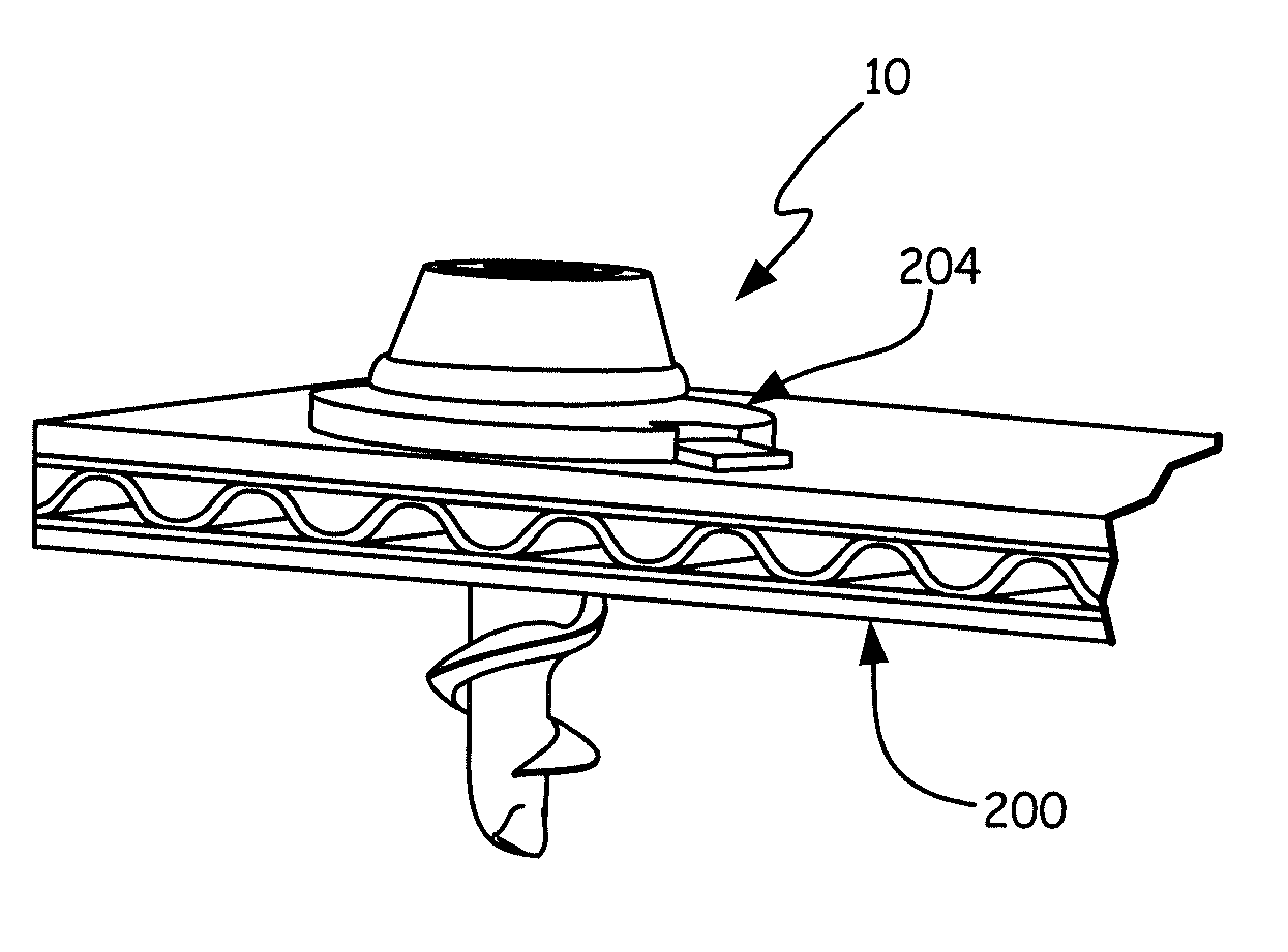
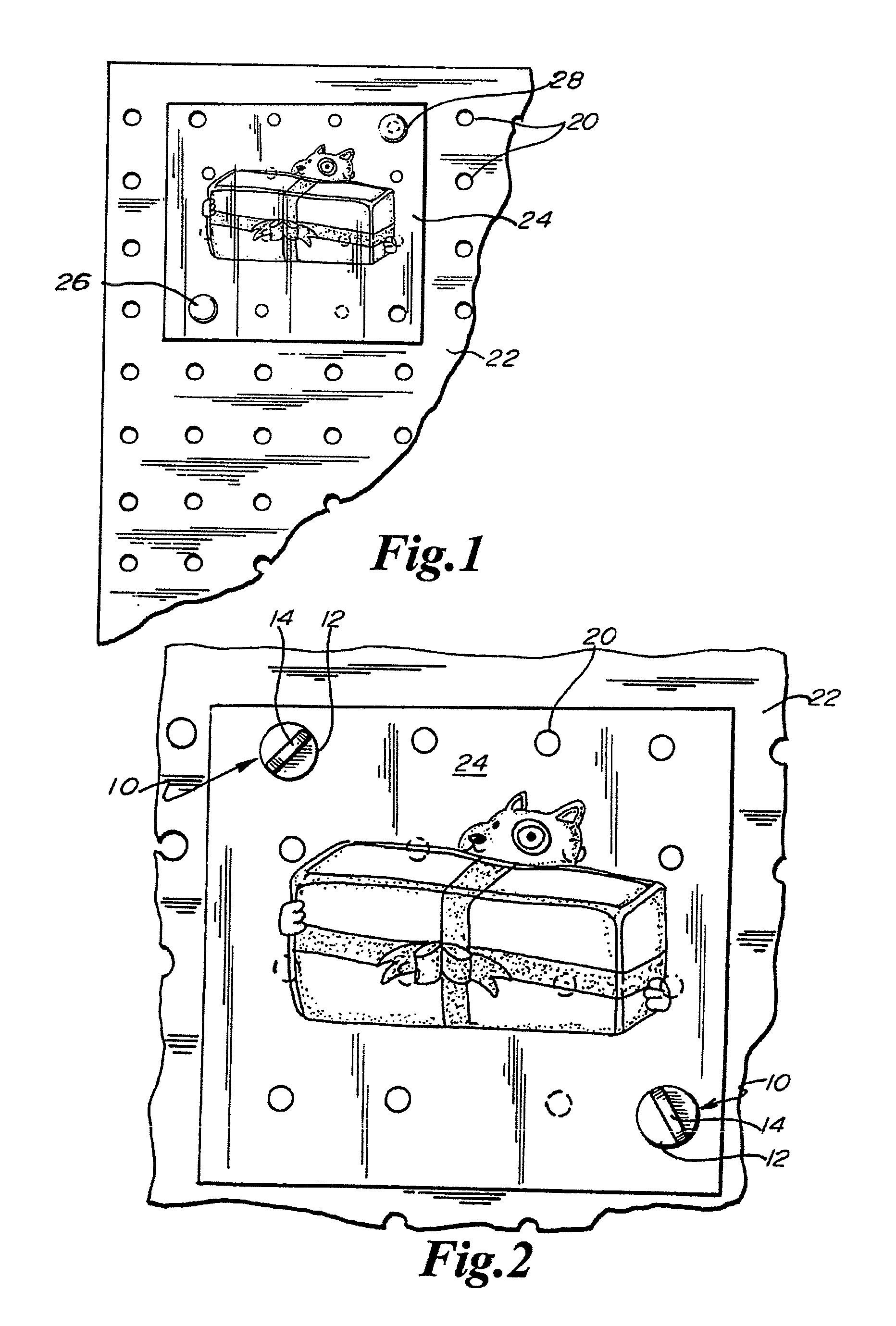
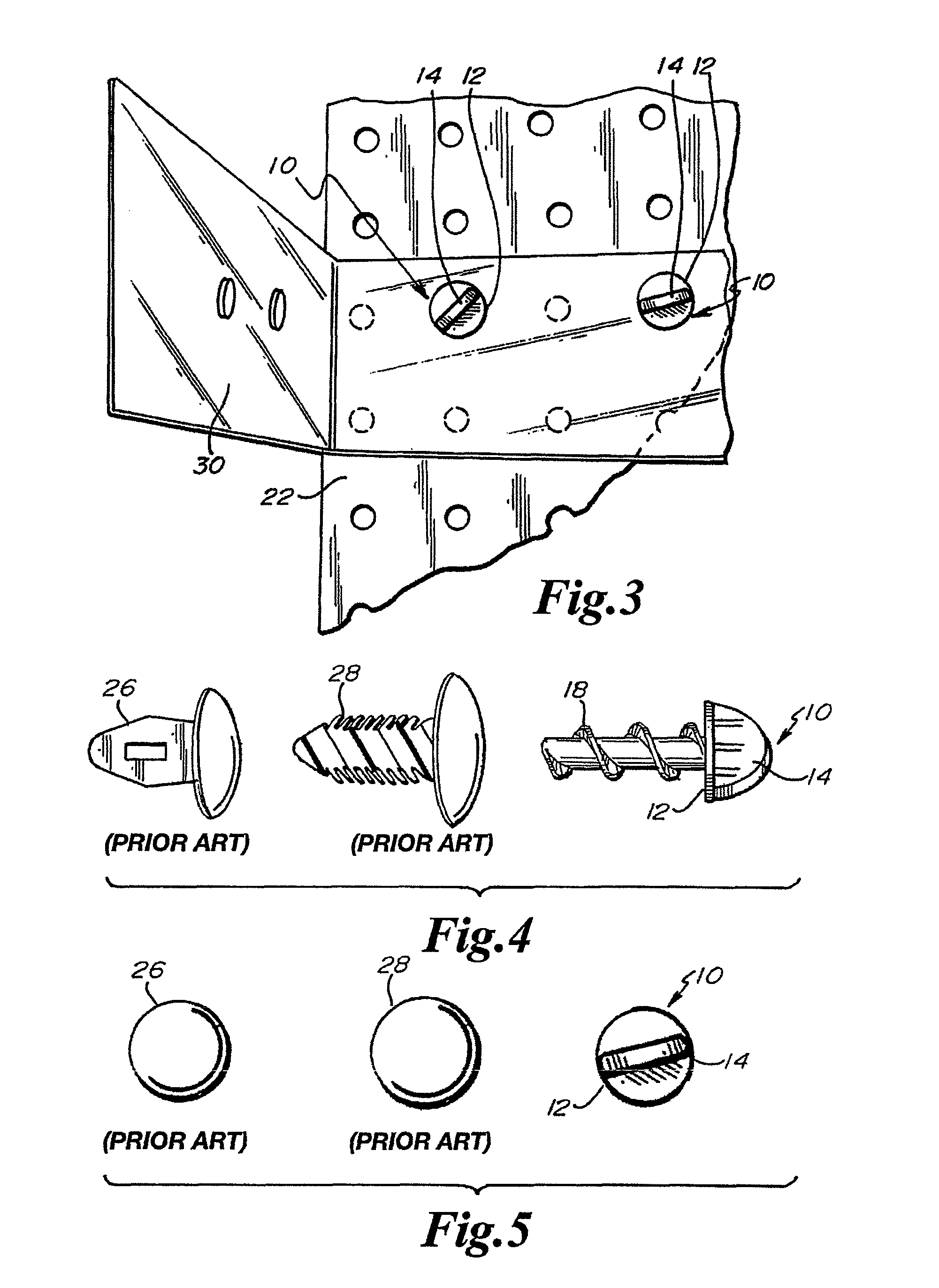
[0046]In the Figures, various configurations of a fastener / connector clip 10 are shown. The clip 10 includes a head 12 having a thumbscrew protrusion 14, and a body 16 with spaced apart threads 18. The clip 10 is of various widths and lengths to accommodate, most preferably, different width and depth of holes 20 in peg board 22. Most preferably, the clip 10 is sized to accommodate ¼ inch peg board. Of course, variations of size, orientation, and application of the clips 10 are within the scope of the present invention. In particular, the clips 10 are not necessarily limited to use with peg board.

[0047]As seen best in FIGS. 1 and 6, a conventional peg board 22 is shown which is used to display advertising and promotional material such as the poster 24 shown in FIG. 1. Prior art clips, such as canoe clips 26 or Christmas tree clips 28, as described in the Background are shown securing two corners of the poster 24. As described, the prior art clips 26, 28 are generally effective at sec...


PUM


Abstract

A clip includes a head having a thumbscrew protrusion and a body with spaced apart threads. The clip is of various widths and lengths to accommodate, most preferably, different widths and depths of holes in peg board. Most preferably, the clip is sized to accommodate ¼ inch peg board, and is used to releasably secure items such as advertisements and promotional material to the peg board.

Description

CROSS REFERENCE TO RELATED APPLICATION[0001]The present application claims priority to, and incorporates by reference hereto, U.S. Provisional Application No. 61 / 063,967 of the same title, filed Feb. 6, 2008, and U.S. patent application Ser. No. 12 / 322,755 of the same title, filed Feb. 6, 2009, and U.S. patent application Ser. No. 12,710,776 of the same title, filed Feb. 23, 2010.FIELD OF THE INVENTION[0002]This invention relates to a connector or fastener for use with a display board. In particular, the invention relates to a reusable fastener designed to secure material such as promotional posters, displays, and brackets to a peg board backing in a retail environment. Of course, a person of ordinary skill in the art will understand that the invention is not necessarily so limited.BACKGROUND OF THE INVENTION[0003]In retail environments promotional and marketing display material is commonly affixed to open wall space near, or in anticipation of the arrival of, goods or services for ...

Claims


Application Information

Patent Timeline
31 Dec 2013
Publication
US8616091B2
IPC
B25B13/48; F16B12/10
CPC
F16B12/10; F16B15/06; F16B15/02; F16B35/06; F16B12/24; F16B21/02; B43M15/00; A47F5/11
Inventors
ANDERSON, RICK, DAVID