Mill liner assembly

a technology of liner assembly and mill liner, which is applied in the field of mill liner assembly, can solve the problems of difficult removal of lifter bars alone (i.e., without removing some or all of the shell plates) and may have a substantially shorter useful life, and achieve the effects of preventing the adhesion of the shell preventing the adhesion of the shall plate and the lifter bar to each other, and preventing the adhesion of the shall

Active Publication Date: 2014-01-07
POLYCORP
View PDF31 Cites 16 Cited by
  • Summary
  • Abstract
  • Description
  • Claims
  • Application Information

AI Technical Summary

Problems solved by technology

For instance, the lifter bars may have a substantially shorter useful life than the shell plates on which the lifter bar is at least partially positioned.
However, in practice, removal of the lifter bars alone (i.e., without removing some or all of the shell plates) is usually very difficult.

Method used


Image

  • Mill liner assembly
  • Mill liner assembly
  • Mill liner assembly

Examples


Embodiment Construction

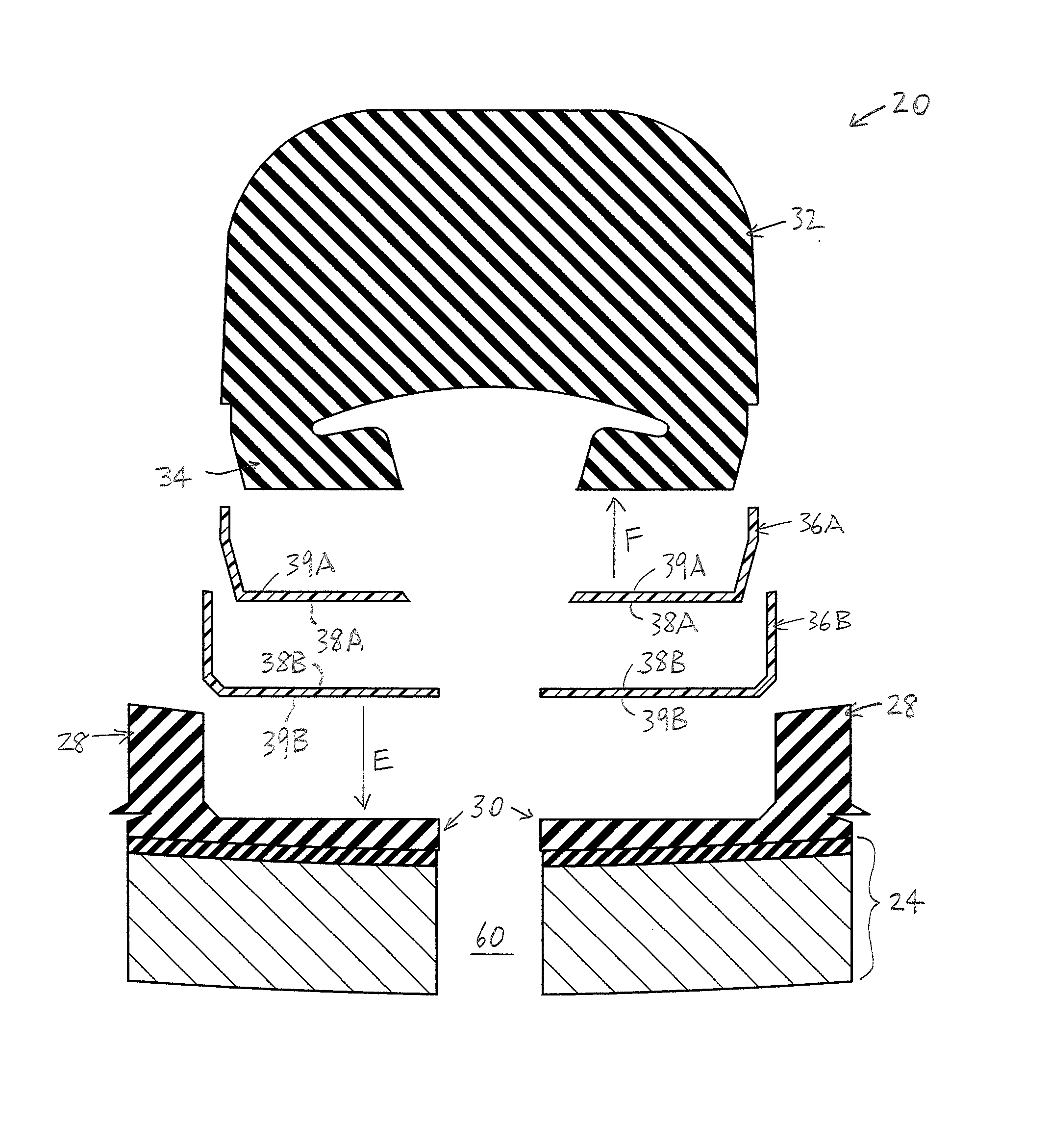
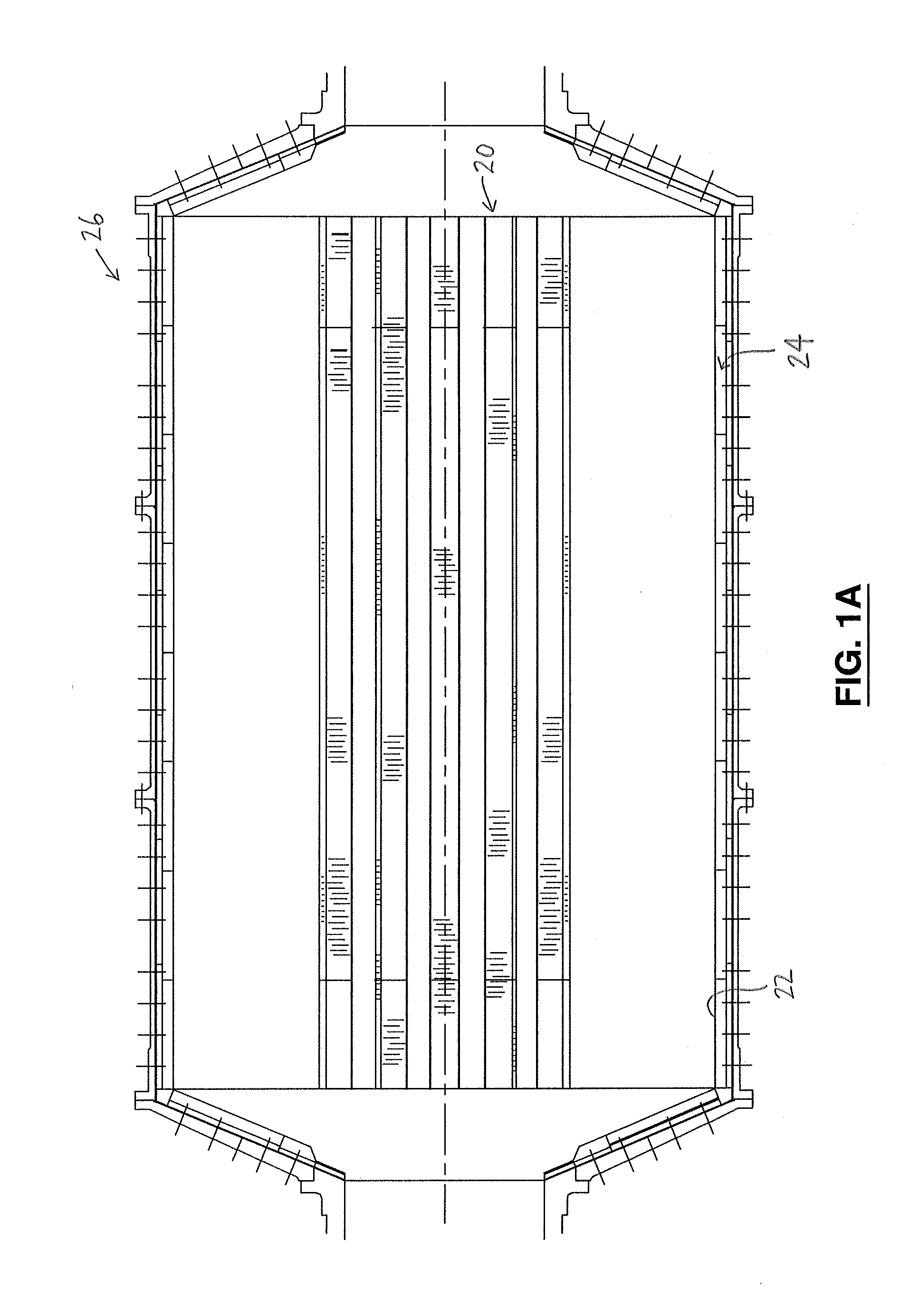
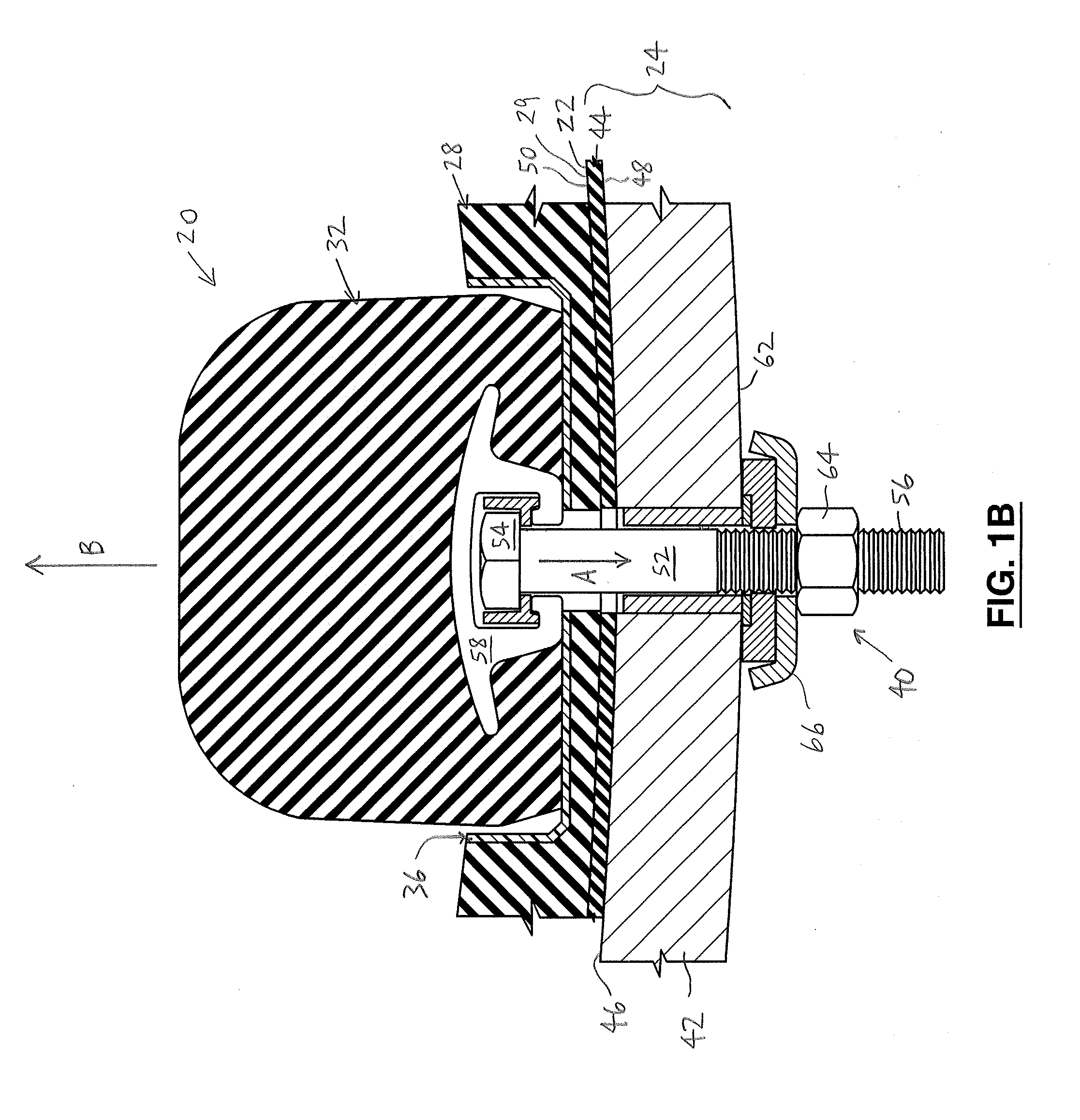
[0035]In the attached drawings, like reference numerals designate corresponding elements throughout. Reference is first made to FIGS. 1A-1E, 4A, 4B, and 7A-10 to describe an embodiment of a mill liner assembly of the invention referred to generally by the numeral 20. The mill liner assembly 20 is for mounting on an inner diameter 22 of a shell 24 of a grinding mill 26 (FIG. 1A). In one embodiment, the mill liner assembly 20 preferably includes one or more shell plates 28 for engagement with the shell 24, each shell plate 28 having a cooperating portion 30 (FIGS. 1C, 1D, 4B, 7B). It is also preferred that the mill liner assembly 20 includes one or more lifter bars 32, each lifter bar 32 having a mounting portion 34 thereof (FIG. 1D). The mounting portion 34 preferably is receivable on the cooperating portion 30, as will be described. Preferably, the mill liner assembly 20 also includes one or more layers 36 including one or more substantially non-resilient materials and a substantial...


PUM


Abstract

A mill liner assembly for mounting on an inner diameter of a shell of a grinding mill. The mill liner assembly includes one or more shell plates for engagement with the shell, each of the shell plates having a cooperating portion thereof, and one or more lifter bars, each of the lifter bars having a mounting portion thereof, the mounting portion being receivable on the cooperating portion. The mill liner assembly also includes one or more layers having one or more substantially non-resilient materials and a substantially non-sticking surface. The layer is at least partially positioned on at least a first selected one of the cooperating portion and the mounting portion, to position the non-sticking surface thereof for engagement with a second selected one of the cooperating portion and the mounting portion, to impede adhesion of the shell plate and the lifter bar to each other.

Description

[0001]This application claims the benefit of U.S. Provisional Patent Application No. 61 / 432,406, filed on Jan. 13, 2011, and incorporates such provisional patent application in its entirety by reference.FIELD OF THE INVENTION[0002]The present invention is related to a mill liner assembly to be mounted on a shell of a grinding mill, the mill liner assembly including a layer providing a substantially non-sticking surface for impeding adhesion of elements of the mill liner assembly with each other or with the shell.BACKGROUND OF THE INVENTION[0003]As is well known in the art, an inner diameter of a shell of a grinding mill typically is lined with a mill liner, for wear protection, i.e., to protect the shell. The mill liner may include, for instance, shell plates positioned on the inner diameter so as to substantially cover the shell's inner diameter, and lifter bars spaced apart from each other, with the shell plates positioned between the lifter bars and the shell. The heads of bolts ...

Claims


Application Information

Patent Timeline
Patent Type & Authority Patents(United States)
IPC IPC(8): B02C17/14
CPCB02C17/225
Inventor MEPHAM, ROBERTPAGE, DAVID J.KUMAR, PRAMOD
Owner POLYCORP
Why Eureka
Try Eureka