Fundus observation apparatus

a technology of observation apparatus and telescope, which is applied in the field offundus observation apparatus, can solve the problems of improvement of eyesight, inability to determine whether or not, and other problems, and achieve the effect of improving eyesigh

Active Publication Date: 2014-01-07
KK TOPCON
View PDF17 Cites 11 Cited by
  • Summary
  • Abstract
  • Description
  • Claims
  • Application Information

AI Technical Summary

Benefits of technology

[0042]According to the fundus observation apparatus related to the present invention, an image of the scanning region of the signal light on the fundus can be formed with said scanning region being superposed on the projection region of the visual target for measuring eyesight, and it is possible to measure the eyesight in the projection region and then store the formed image and the measured eyesight value while associating them with each other, allowing an image of the eyesight measurement site of the fundus to be obtained.

Problems solved by technology

This is due to the fact that the main purpose of treatment is the improvement of eyesight, and the change in the morphology of the fundus (for example, hole shrinkage due to treatment of the macular hole) can be confirmed by the fundus observation apparatus, but it cannot be determined whether or not the change in the morphology results in improvement of eyesight without relying on eyesight measurement.

Method used


Image

  • Fundus observation apparatus
  • Fundus observation apparatus
  • Fundus observation apparatus

Examples


Embodiment Construction

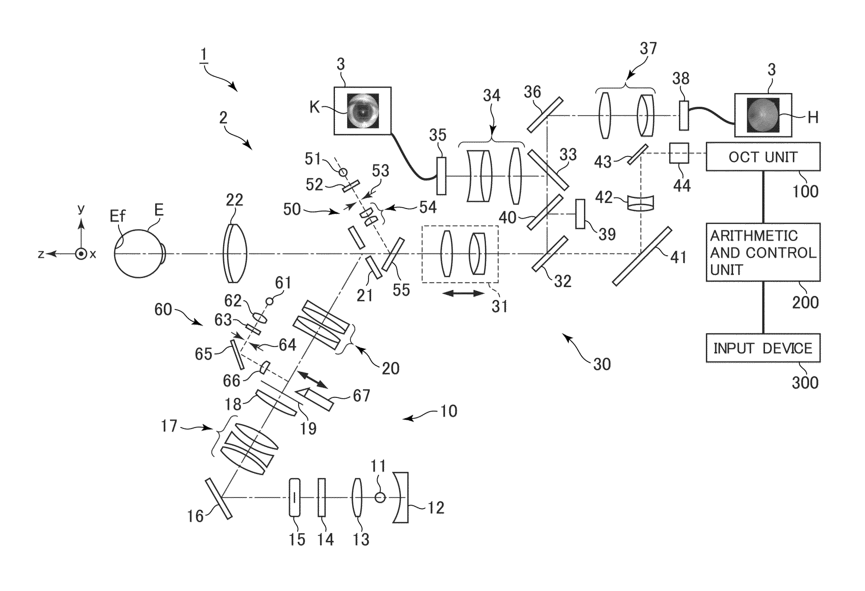
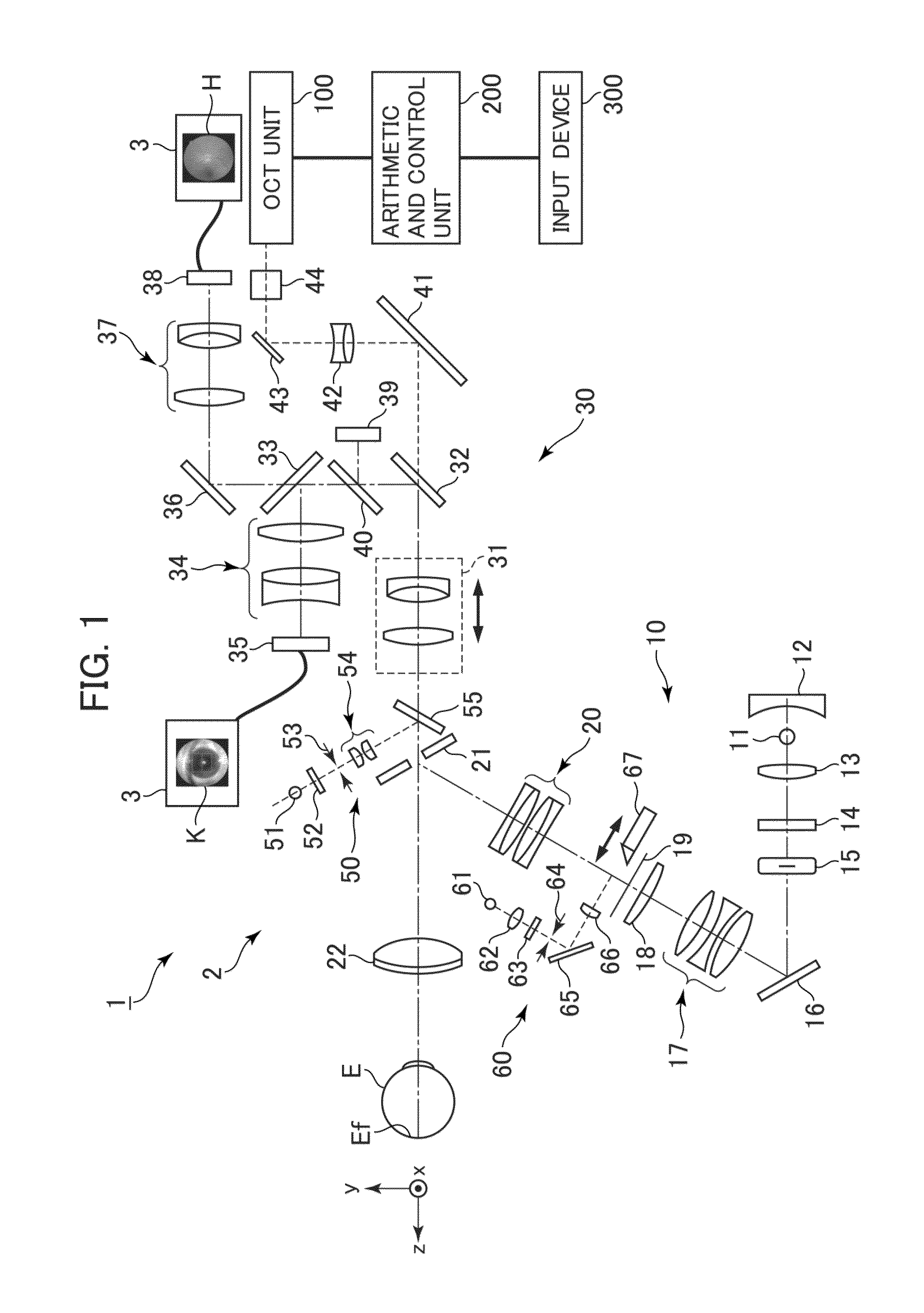
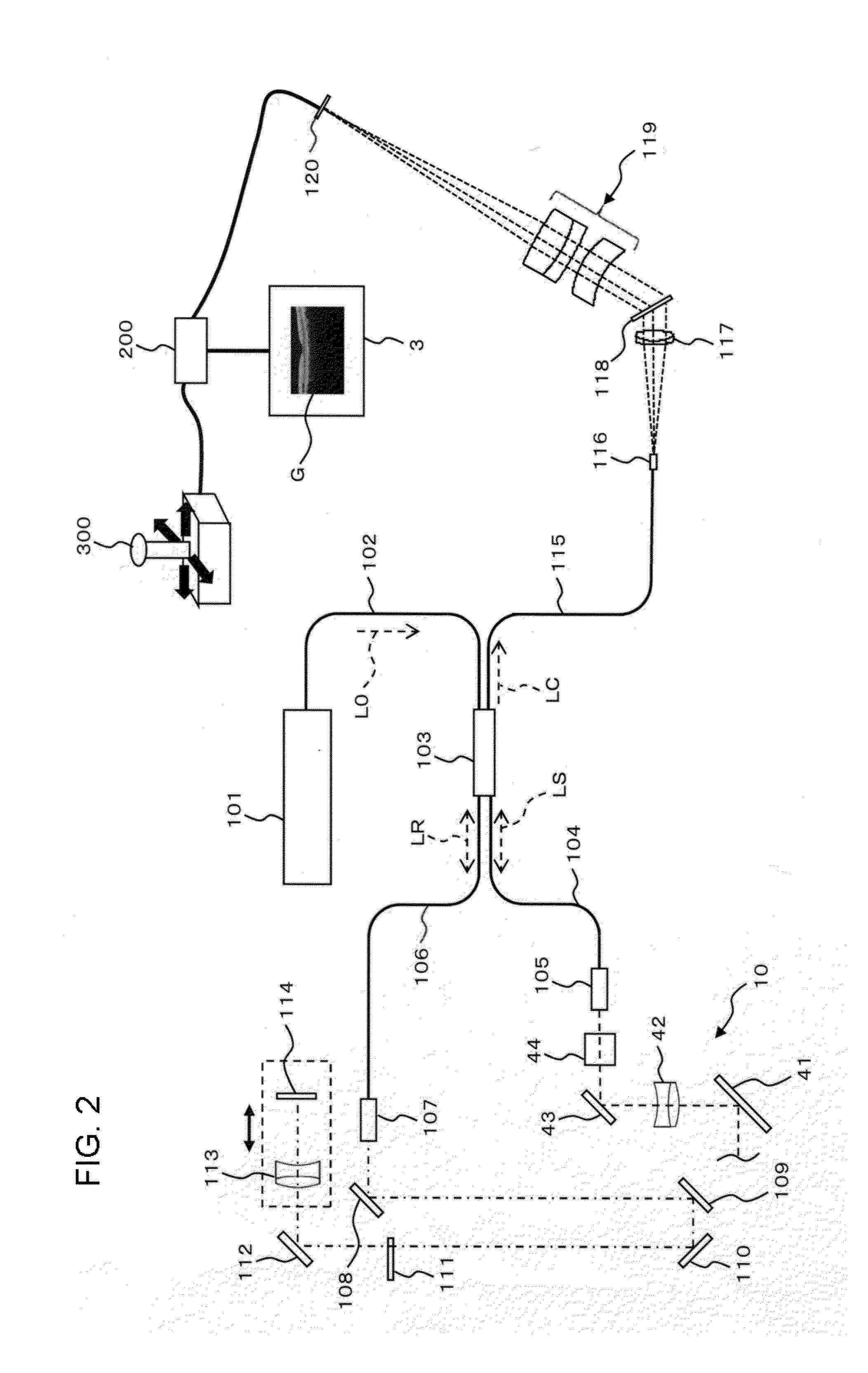
[0053]An example of an embodiment of a fundus observation apparatus according to the present invention will be described in detail with reference to the drawings.

[0054]The fundus observation apparatus according to the present invention forms tomographic images of a fundus using optical coherence tomography. Optical coherence tomography of an arbitrary type involving scanning with a signal light such as a Fourier Domain type, a swept source type, etc. are applicable to the fundus observation apparatus. It should be noted that an image obtained by optical coherence tomography is sometimes referred to as an OCT image. Furthermore, a measuring action for forming an OCT image is sometimes referred to as an OCT measurement.

[0055]In the following embodiments, a configuration to which a Fourier-Domain-type is applied will be described in detail. To be specific, in these embodiments, similar to a device disclosed in Patent Document 5, a fundus observation apparatus that is capable of obtaini...


PUM


Abstract

The controller 210 changes the projection region of the Landolt ring T on the fundus Ef by changing, based on the scanning region R, the relative display position of the Landolt ring T and the fixation target V on the LCD 39, thereby overlapping the scanning region R and the projection region each other. Under this condition, the fundus observation apparatus 1 executes the eyesight measurement and OCT measurement, obtains the eyesight value at the site of interest of the fundus Ef, and forms a tomographic image of the fundus Ef in the scanning region R. The controller 210 stores in the storage 212 the eyesight value at the site of interest and the tomographic image corresponding to the scanning line closest to the measurement position of eyesight while correlating them with each other, and allows them to be displayed on the display device 3.

Description

TECHNICAL FIELD[0001]The present invention relates to a fundus observation apparatus configured to form images of a fundus of an eye by using optical coherence tomography.BACKGROUND ART[0002]In recent years, optical coherence tomography that forms images of the surface morphology and internal morphology of an object by using a light beam from a laser light source or the like has attracted attention. Unlike an X-ray CT apparatus, optical coherence tomography is noninvasive to human bodies, and is therefore expected to be utilized in the medical field and biological field.[0003]Patent Document 1 discloses a device to which optical coherence tomography is applied. This device has such a configuration that: a measuring arm scans an object by a rotary deflection mirror (a Galvano mirror); a reference arm is provided with a reference mirror; and an interferometer is mounted at the outlet to analyze, by a spectrometer, the intensity of an interference light of light fluxes from the measure...

Claims


Application Information

Patent Timeline
Patent Type & Authority Patents(United States)
IPC IPC(8): A61B3/14A61B3/12
CPCA61B3/14A61B3/032A61B3/1225A61B3/102A61B3/12
Inventor HAYASHI, TAKEFUMI
Owner KK TOPCON
Why Eureka
Try Eureka