Imaging device and electronic apparatus with the same

a technology of electronic equipment and imaging device, which is applied in the direction of cameras, instruments, printers, etc., can solve the problems of increasing the cost, complicated inner structure of the apparatus, and difficult to incorporate the focus adjustment mechanism in a compact and flexible electronic apparatus such as a cellular phone, and achieves the effect of simple and easy construction

Inactive Publication Date: 2005-07-07
ASAHI KOGAKU KOGYO KK
View PDF9 Cites 10 Cited by
  • Summary
  • Abstract
  • Description
  • Claims
  • Application Information

AI Technical Summary

Benefits of technology

[0006] An object of the present invention is to produce an imaging device, a method for imaging, and an electronic apparatus with the imaging device such as a digital camera that is a simple and easy to construct, and is capable of obtaining a focused image.

Problems solved by technology

On the other hand, when using the auto / manual focus mechanism, the inner structure of the apparatus becomes complicated because of the focus adjustment mechanism, which raises the cost.
Further, it is difficult to incorporate the focus adjustment mechanism in a compact and flexible electronic apparatus such as a cellular phone.

Method used


Image

  • Imaging device and electronic apparatus with the same
  • Imaging device and electronic apparatus with the same
  • Imaging device and electronic apparatus with the same

Examples


first embodiment

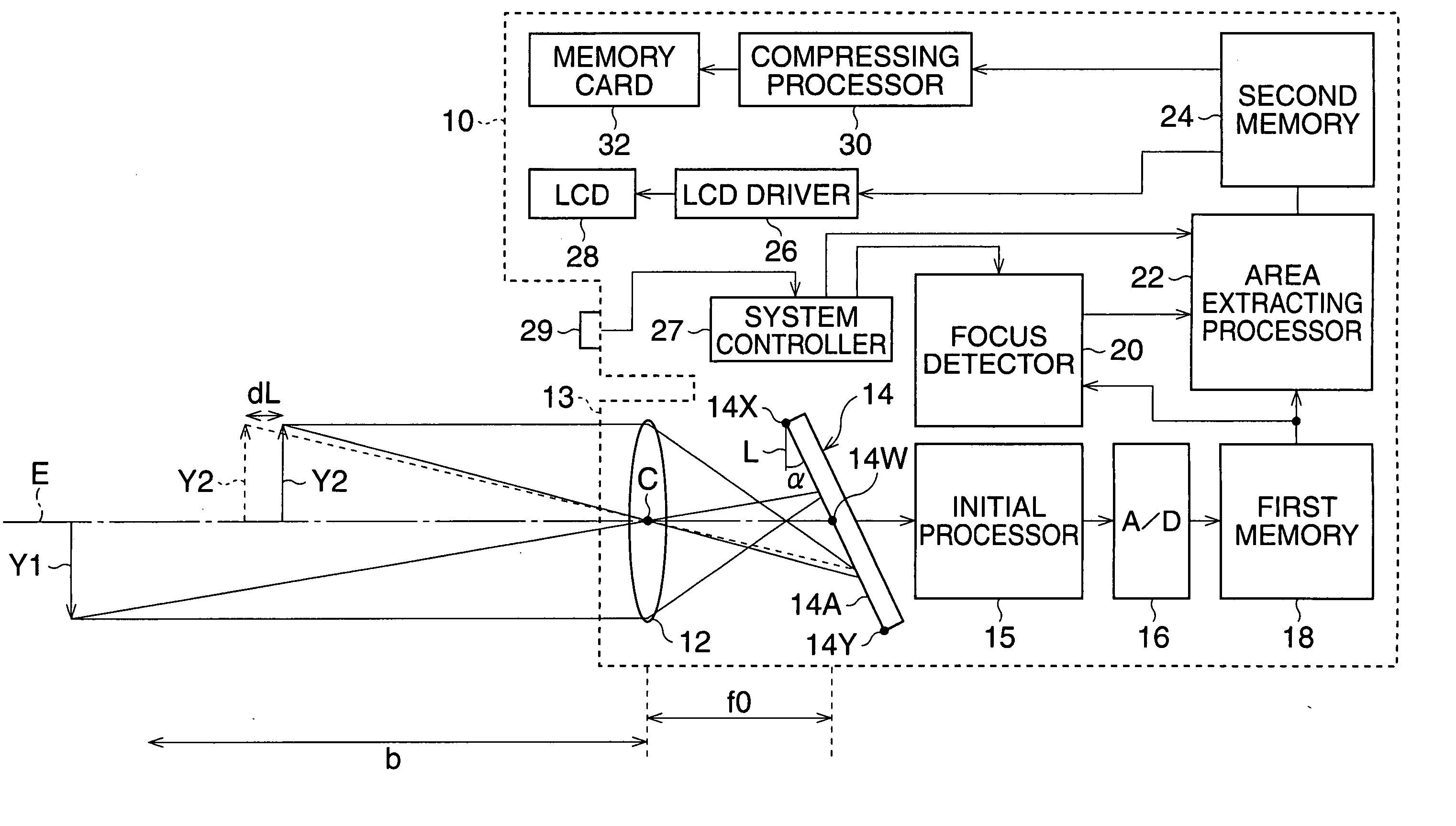
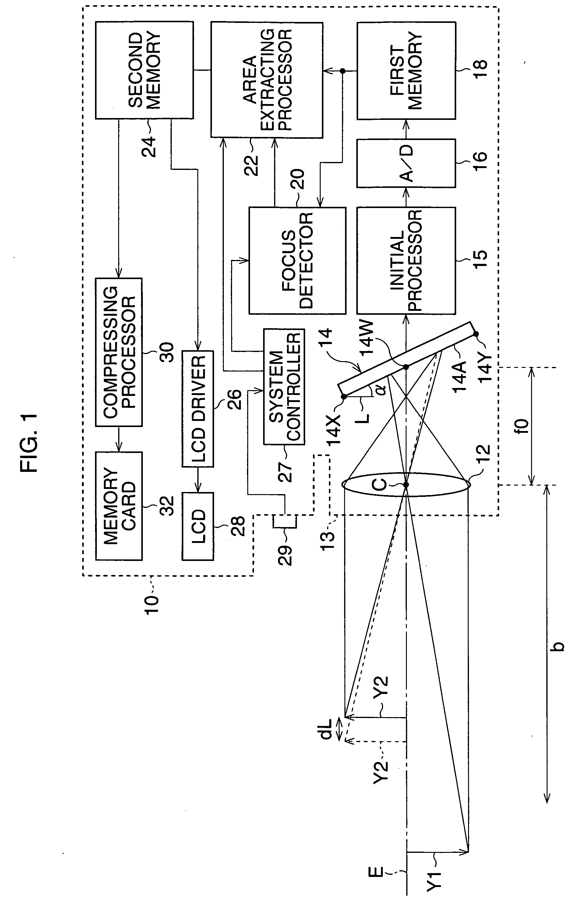
[0033]FIG. 1 is a block diagram of a digital still camera according to a

[0034] A digital camera 10 is capable of displaying a movie image and recording a still image, and has a photographing optical system 12, a CCD 14, a system controller 27, and an LCD 28. The photographing optical system 12 is a single focus optical system without a focusing lens. The magnification of the optical photographing system 12 is set to a standard magnification (for example, less than {fraction (1 / 10)}). The system controller 27 controls the camera 10. The photographing optical system 12 is provided in a lens barrel 13 of the camera 10, and forms an object image on a photo-receiving area 14A of the CCD 14. The CCD 14 is arranged to be inclined relative to the direction L, which is perpendicular to an optical axis E of the photographing optical system 12, by a given angle α. Further, the CCD 14 is arranged such that the center of the photo-receiving area 14W passes through the optical axis E. Note that, ...

third embodiment

[0056]FIG. 9 is a view showing an arrangement of the CCD according to the

[0057] The first end point 14X of the photo-receiving area 14A corresponds to an image-point of an object at infinity. The second end point 14Y corresponds to an image-point of an object positioned on a closest focusing distance. Herein, the inclined angle is calculated in a condition that an image of an object in the shooting range (from the closest focusing distance to the infinity) is focused in a part-area of the photo-receiving area 14A.

[0058] In FIG. 9, a focus distance is designated by “f”; a distance from the first end point 14X to the second end point 14Y along the optical axis E, is designated by “Δf”; a height of an object Y3 from the optical axis E is designated by “H”; a cross point of the object Y3 and the optical axis E is designated by “S2”; the top point of the object “Y3” is designated by “S1”; and the principle point of the optical photographing system 12 is designated by “C”. An imaging pla...

fourth embodiment

[0079] When the inclined angle is designated by “θ4” the inclined angle “θ4” is obtained by using “(hc−hp)” in place of “hc”, similarly to the

θ4=sin−1(((Δf / 2−d1f / D) (2f+Δf)) / ((hc−hp−d1) (f+Δf)))  (29)

[0080] With reference to FIG. 14, an imaging device according to the seventh embodiment is explained. In the seventh embodiment, the radius of the circle of confusion formed at the upper end point is the same as that of the circle of confusion formed at the lower endpoint. Other constructions of the imaging device are the same as those of the fifth embodiment shown in FIGS. 11 to 13.

[0081]FIG. 14 is a view showing an arrangement of the CCD 14 according to the seventh embodiment. When the radius “d1” of the circle of confusion “c1”, corresponding to the first end point 14X, is equal to the radius “d2” of the circle of confusion “c2”, corresponding to the second end point 14Y, the center 14W of the photo-receiving area 14A does not coincide with a point distant from the focal plane FS b...


PUM


Abstract

An electronic apparatus with an imaging device has a photographing optical system that forms an object image, an image pick-up device that has a photo-receiving area and generates image-pixel signals from the object image formed on the photo-receiving area. The photo-receiving area is inclined relative to a direction perpendicular to an optical axis by a given angle. The electronic apparatus has an extracting processor that extracts a focused-image from the object image as focused-image data on the basis of the image-pixel signals, a recording processor that records the focused-image data in a memory; and a displaying processor that displays the focused-image on a display in accordance with the focused-image data.

Description

BACKGROUND OF THE INVENTION [0001] 1. Field of the Invention [0002] The present invention relates to an imaging device and an electronic apparatus with the imaging device, such as a digital still or movie camera, a digital specialized camera for security or TV conversation, a cellular phone with a camera, and so on. Especially, it relates to a focus adjustment of the imaging device. [0003] 2. Description of the Related Art [0004] In the digital camera, a pan-focus or an auto / manual focus is performed to adjust the focus. In the case of the pan-focus, a lens with a short focus length is used, and the diameter of an iris is reduced so as to have a small F number, whereby both an object close to the camera or an object far away from the camera can be focused. On the other hand, in the case of the auto / manual focus, a focusing lens is incorporated in the camera, and a focus adjustment is performed by shifting the focusing lens along the optical axis. Further, when photographing a big an...

Claims


Application Information

Patent Timeline
Patent Type & Authority Applications(United States)
IPC IPC(8): G02B7/28G03B13/36G02B7/36G02B27/64G03B5/08G03B17/18H04N5/225H04N5/232H04N101/00
CPCH04N5/23212G02B27/64G03B3/04H04N23/00
Inventor ABE, NOBUAKI
Owner ASAHI KOGAKU KOGYO KK
Why Eureka
Try Eureka