Imaging device and electronic apparatus with the same
a technology of electronic equipment and imaging device, which is applied in the direction of cameras, instruments, printers, etc., can solve the problems of increasing the cost, complicated inner structure of the apparatus, and difficult to incorporate the focus adjustment mechanism in a compact and flexible electronic apparatus such as a cellular phone, and achieves the effect of simple and easy construction
- Summary
- Abstract
- Description
- Claims
- Application Information
AI Technical Summary
Benefits of technology
Problems solved by technology
Method used
Image
Examples
first embodiment
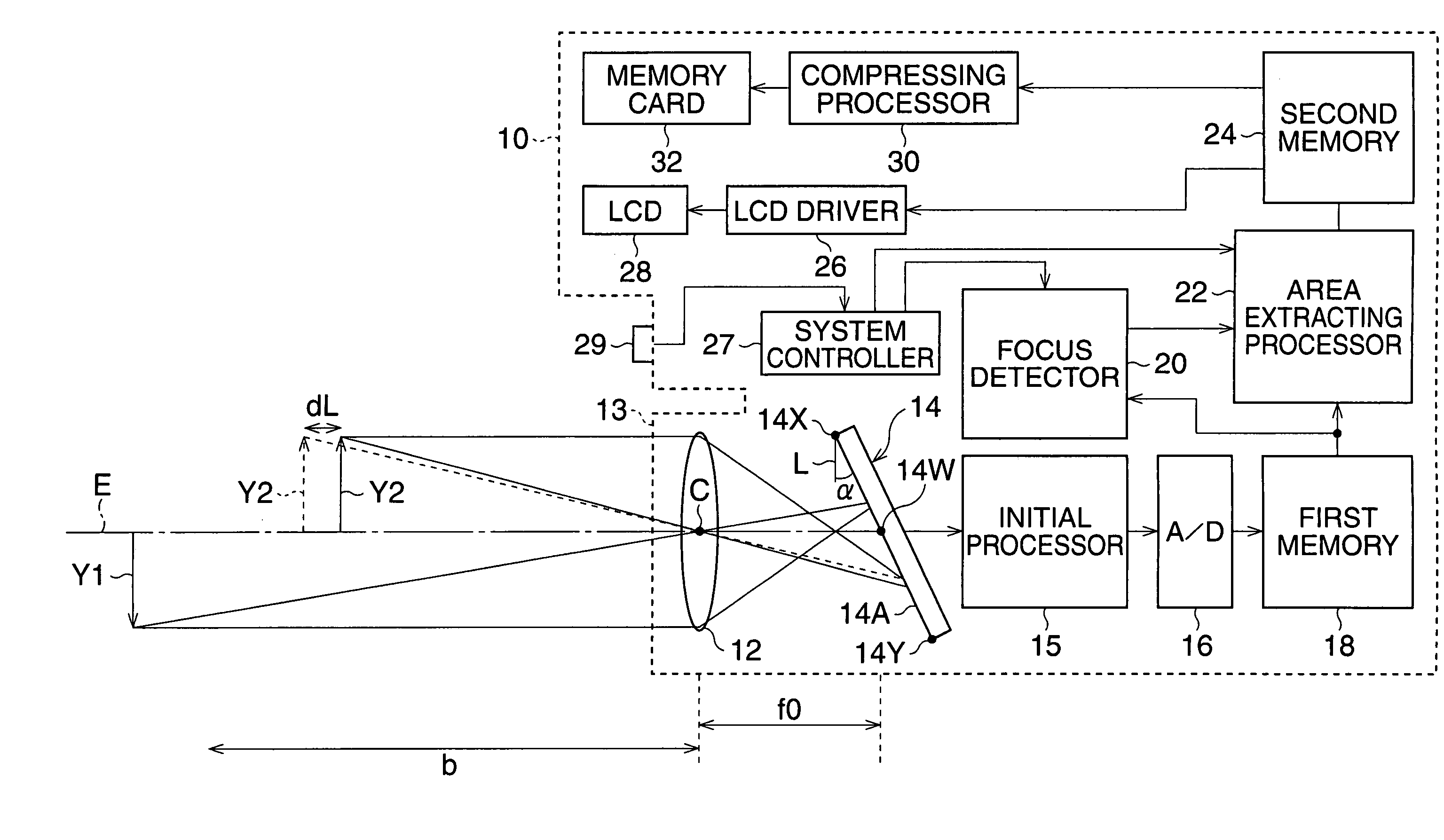
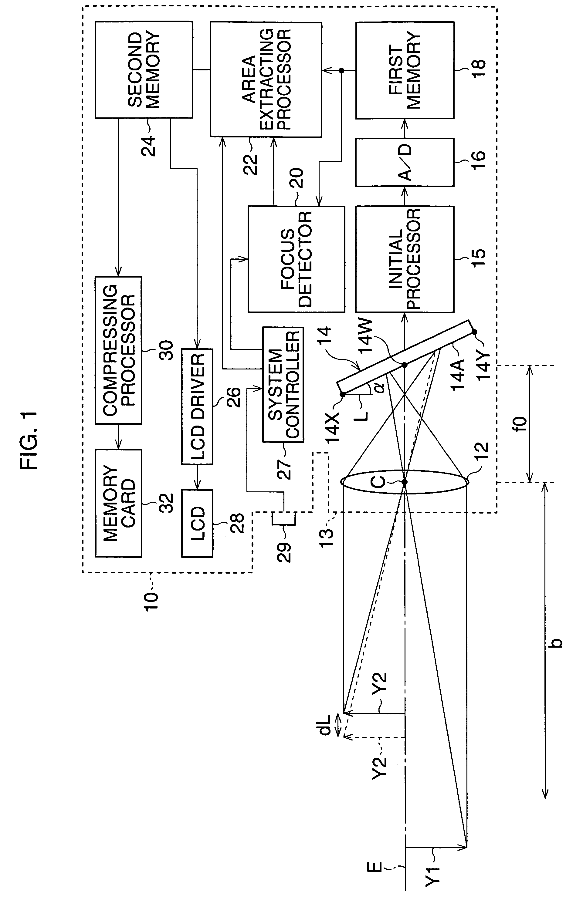
[0033]FIG. 1 is a block diagram of a digital still camera according to a
[0034]A digital camera 10 is capable of displaying a movie image and recording a still image, and has a photographing optical system 12, a CCD 14, a system controller 27, and an LCD 28. The photographing optical system 12 is a single focus optical system without a focusing lens. The magnification of the optical photographing system 12 is set to a standard magnification (for example, less than 1 / 10). The system controller 27 controls the camera 10. The photographing optical system 12 is provided in a lens barrel 13 of the camera 10, and forms an object image on a photo-receiving area 14A of the CCD 14. The CCD 14 is arranged to be inclined relative to the direction L, which is perpendicular to an optical axis E of the photographing optical system 12, by a given angle α. Further, the CCD 14 is arranged such that the center of the photo-receiving area 14W passes through the optical axis E. Note that, the angle α is...
third embodiment
[0056]FIG. 9 is a view showing an arrangement of the CCD according to the
[0057]The first end point 14X of the photo-receiving area 14A corresponds to an image-point of an object at infinity. The second end point 14Y corresponds to an image-point of an object positioned on a closest focusing distance. Herein, the inclined angle is calculated in a condition that an image of an object in the shooting range (from the closest focusing distance to the infinity) is focused in a part-area of the photo-receiving area 14A.
[0058]In FIG. 9, a focus distance is designated by “f”; a distance from the first end point 14X to the second end point 14Y along the optical axis E, is designated by “Δf”; a height of an object Y3 from the optical axis E is designated by “H”; a cross point of the object Y3 and the optical axis E is designated by “S2”; the top point of the object “Y3” is designated by “S1”; and the principle point of the optical photographing system 12 is designated by “C”. An imaging plane ...
fourth embodiment
[0081]When the inclined angle is designated by “θ4” the inclined angle “θ4” is obtained by using “(hc−hp)” in place of “hc”, similarly to the
θ4=sin−1(((Δf / 2−d1f / D)(2f+Δf)) / ((hc−hp−d1)(f+Δf))) (29)
[0082]With reference to FIG. 14, an imaging device according to the seventh embodiment is explained. In the seventh embodiment, the radius of the circle of confusion formed at the upper end point is the same as that of the circle of confusion formed at the lower endpoint. Other constructions of the imaging device are the same as those of the fifth embodiment shown in FIGS. 11 to 13.
[0083]FIG. 14 is a view showing an arrangement of the CCD 14 according to the seventh embodiment. When the radius “d1” of the circle of confusion “c1”, corresponding to the first end point 14X, is equal to the radius “d2” of the circle of confusion “c2”, corresponding to the second end point 14Y, the center 14W of the photo-receiving area 14A does not coincide with a point distant from the focal plane FS by Δf / 2...
PUM
 Abstract
Description
Claims
Application Information
 - R&D
- Intellectual Property
- Life Sciences
- Materials
- Tech Scout
- Unparalleled Data Quality
- Higher Quality Content
- 60% Fewer Hallucinations
Browse by: Latest US Patents, China's latest patents, Technical Efficacy Thesaurus, Application Domain, Technology Topic, Popular Technical Reports.
© 2025 PatSnap. All rights reserved.Legal|Privacy policy|Modern Slavery Act Transparency Statement|Sitemap|About US| Contact US: help@patsnap.com


