
Vehicle driving system

a driving system and vehicle technology, applied in the direction of machines/engines, engine starters, gearing, etc., can solve the problems of increasing production costs, limited space for installing engines, and increasing the longitudinal dimension of engines along the crankshaft, so as to enhance the degree of freedom in installing driving systems in vehicles

Inactive Publication Date: 2005-09-27
HONDA MOTOR CO LTD
View PDF22 Cites 8 Cited by
  • Summary
  • Abstract
  • Description
  • Claims
  • Application Information

AI Technical Summary

Benefits of technology

[0013]It is an object of the invention to provide a vehicle driving system which can drive the auxiliary unit while the engine is stopped, start up the engine and charge the battery with a single motor, to thereby have a simple and easy construction and good mounting properties.
[0036]According to the sixth aspect of the invention, there is provided with the vehicle driving system according to any of claims 1 to 5, wherein said drive shaft and said auxiliary unit are disposed on different axes, since the driving system and the auxiliary unit can be laid out according to the available installation space of the vehicle, the degree of freedom in installing the driving system in the vehicle can be enhanced.

Problems solved by technology

However, mounting the auxiliary motor only for driving the auxiliary unit such as the air conditioner compressor causes a problem that the number of components is increased, to thereby increase the production costs.
In addition, in the case where the motor functioning as the starter is used to drive the auxiliary unit, providing the clutch on the crankshaft of the engine results in an increase in the longitudinal dimension of the engine along the crankshaft.
This causes a big problem in a case where a space for installing the engine is limited.
Furthermore, in a case where the driving system including the motor and the planetary gear mechanism is disposed substantially in parallel with the crankshaft, there is a problem that the engine installation space is largely limited due to the layout of intake and exhaust manifolds of the engine.

Method used


Image

  • Vehicle driving system
  • Vehicle driving system
  • Vehicle driving system

Examples


Embodiment Construction

[0052]An embodiment of the invention will be described below by reference to the accompanying drawings.

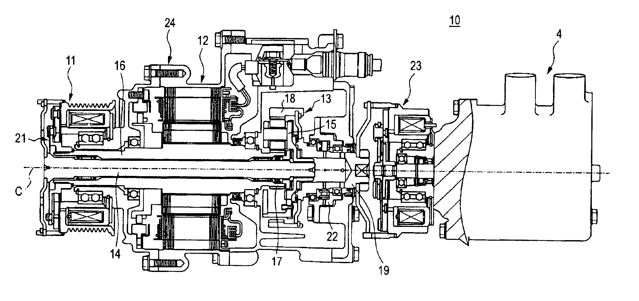
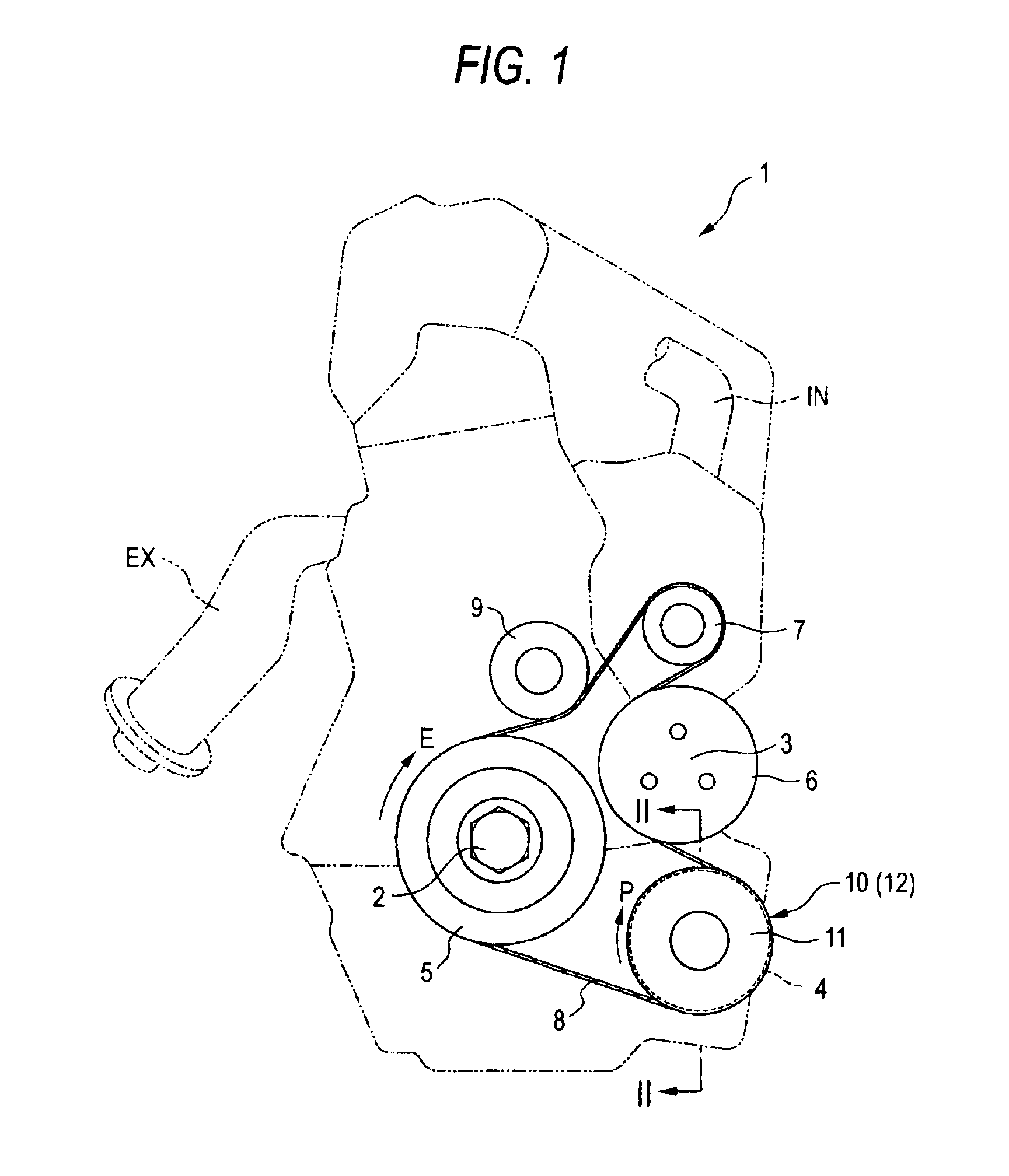
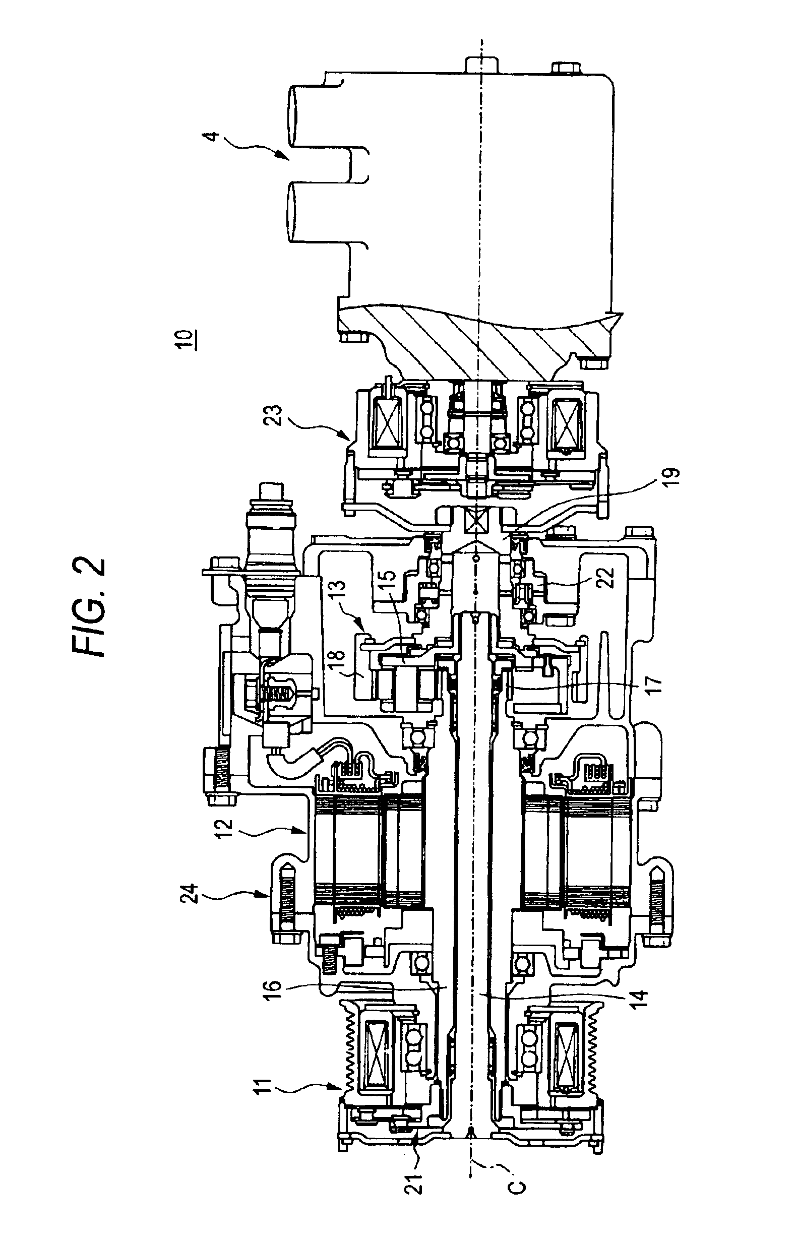
[0053]As shown in FIG. 1, an internal combustion engine 1 according to an embodiment of the invention has a water pump 3 and a driving system 10 which is coaxially connected to an air conditioner compressor 4 on a side of the engine which extends along a longitudinal direction of a crankshaft thereof. The water pump 3, the compressor 4 and the driving system 10 are disposed substantially in parallel with the crankshaft 2 (or are side mounted) so as to avoid the interference with an inlet manifold IN.

[0054]A crankshaft pulley 5 is provided at an end of the crankshaft 2. A belt 8 is wound around the crankshaft pulley 5, a water pump pulley 6 provided on the water pump 3, a pulley 11 provided at one end of the driving system and an idler pulley 7 so as to be able to link them to one another. The driving system 10 is provided with a motor 12, which will be described later. The motor 12...


PUM


Abstract

A vehicle driving system includes a pulley shaft synchronously rotating with a crankshaft of an engine, an auxiliary unit drive shaft driving an auxiliary unit, a planetary gear mechanism portion having elements such as a sun gear, a pinion carrier and a ring gear. The pulley shaft and the auxiliary unit drive shaft are adapted for connection to any two of the elements, respectively. The motor connecting to the remaining element of the planetary gear mechanism portion. A lock-up clutch connecting together the two or more elements of the planetary gear mechanism portion. A one-way clutch for restricting the rotation of the auxiliary unit drive shaft in one direction, wherein the planetary gear mechanism portion, the motor, the lock-up clutch, and the auxiliary unit drive shaft are coaxially disposed in line.

Description

BACKGROUND OF THE INVENTION[0001]1. Filed of the Invention[0002]The present invention relates to a driving system for vehicles which employ an internal combustion engine as a source of driving force, and more particularly to a driving system for vehicles which are designed such that the engine automatically stop idling while they are brought to a stop or hybrid vehicles in which another power source is used to run them with the internal combustion engine being brought to a stop.[0003]2. Description of the Related Art[0004]Vehicles attracting people's attention in recent years are hybrid vehicles and automatic engine idling stop vehicles. The hybrid vehicles are run by a motor using regenerative power and power generated while an engine is driven with the engine being brought to a halt in low-load driving conditions or while the vehicles stops. The automatic engine idling stop vehicles are designed such that the engine automatically stops idling when the vehicles stop.[0005]Some of t...

Claims


Application Information

Patent Timeline
IPC IPC(8): B60K6/02B60K6/04B60K6/00B60K17/04B60H1/32B60K6/365B60K6/383B60K6/48B60W10/30B60W20/00F02N11/00F02N11/04F16H3/72H02K7/116H02K7/18
CPCB60K6/365B60K6/40B60K6/48B60W10/30B60W20/00F04C2240/45F16H3/724Y02T10/6221B60K2006/268Y02T10/62B60K17/00
Inventor FUJIOKA, MASATOTACHIKAWA, JUNYAFUKUSHIMA, TATSUYA
Owner HONDA MOTOR CO LTD
Learn More