Endoscopic surgical device and outer sleeve

a surgical device and endoscope technology, applied in the field of endoscopic surgical devices and overtubes (outer sleeves), can solve the problems of easy enlargement and complexity of the mechanism for interlocking control of the endoscope and the treatment tool, easy prolongation of surgery time, and easy enlargement of the operation for changing the observation position of the endoscope as intended by the surgeon, etc., to achieve excellent operability, stable observation image, and improved operability

Active Publication Date: 2016-06-23
FUJIFILM CORP
View PDF6 Cites 10 Cited by
  • Summary
  • Abstract
  • Description
  • Claims
  • Application Information

AI Technical Summary

Benefits of technology

[0026]According to the invention, the endoscope moves forward and backward with play with respect to the forward and backward movement of the treatment tool. Thus, when the treatment tool has been minutely displaced in the axial direction (when a forward and backward movement of a small amplitude has been performed), the range of an observation image does not change, that is the size of an object to be observed can be prevented from fluctuating, a sense of perspective can be suitably maintained, the amount of forward and backward movement can be recognized from the observation image, and a stable observation image can be provided. Additionally, when the treatment tool has been largely displaced in the axial direction (when a forward and backward movement of a large amplitude has been perfo...

Problems solved by technology

However, the endoscopic surgery system disclosed in JP2004-141486A does not mechanically interlock the endoscope with the treatment tool, and has a problem in which a mechanism for performing interlocking control of the endoscope and the treatment tool is easily enlarged and complicated.
For this reason, there are problems in that it is necessary to ask for an assistant's help in order to change the visual field of the endoscope, the operation for changing the observation position of the endoscope as intended by a surgeon easily becomes complicated, and the surgery time is easily prolonged.
For this reason, there is a problem in that an obs...

Method used


Image

  • Endoscopic surgical device and outer sleeve
  • Endoscopic surgical device and outer sleeve
  • Endoscopic surgical device and outer sleeve

Examples


Embodiment Construction

[0052]A preferred embodiment of the invention will be described below in detail according to the accompanying drawings. In addition, any drawing may illustrate main parts in an exaggerated manner for description, and may have dimensions different from actual dimensions.

[0053]

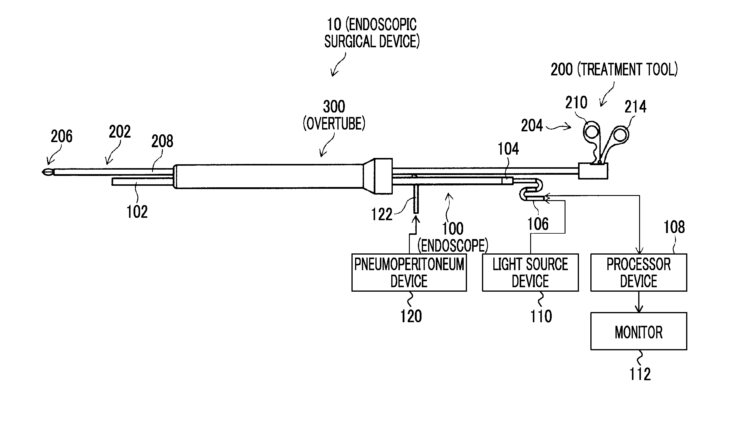
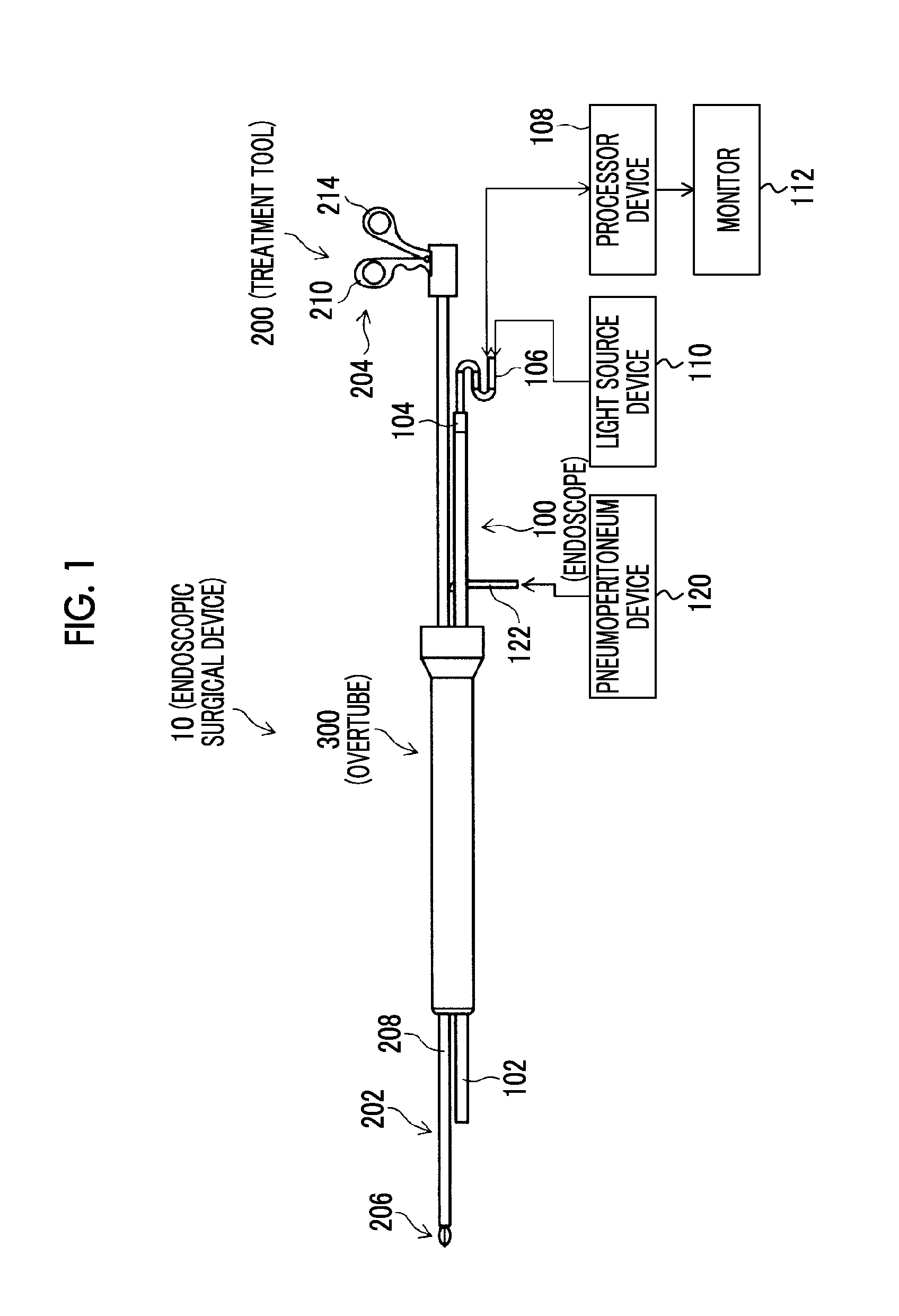
[0054]FIG. 1 is a schematic configuration diagram of an endoscopic surgical device related to the invention. As illustrated in FIG. 1, an endoscopic surgical device 10 includes an endoscope 100 that observes the inside of a patient's body cavity, a treatment tool 200 for inspecting or treating an affected part within the patient's body cavity, and an overtube 300 (guide member) that guides the endoscope 100 and the treatment tool 200 into the body cavity.

[0055]

[0056]The endoscope 100 includes an elongated insertion part (hereinafter referred to as “endoscope insertion part”) 102 that is, for example, a hard endoscope, such as a laparoscope, and that is inserted into a body cavity, and an operating part 104 that ...


PUM


Abstract

Provided is an endoscopic surgical device and an overtube with which a surgeon can easily obtain a desired image and in which operability is high. The overtube includes a slider within an overtube body, which guides an endoscope and a treatment tool into a body cavity. An endoscope-coupled part and a treatment tool-coupled part are provided inside the slider, and the slider has a dead zone where the forward and backward movement of either the endoscope or the treatment tool does not interlock with the movement of the other and a sensing zone where the forward and backward movement of either the endoscope or the treatment tool interlocks with the movement of the other. The overtube body is configured to allow the treatment tool to rotate around an axis thereof without changing the positional relationship of the endoscope and the treatment tool with respect to the overtube body.

Description

CROSS-REFERENCE TO RELATED APPLICATIONS[0001]The present application is a Continuation of PCT International Application No. PCT / JP2014 / 072989 filed on Sep. 2, 2014 claiming priority under 35 U.S.C. §119(a) of U.S. Provisional Application No. 61 / 873,183 filed on Sep. 3, 2013. Each of the above applications is hereby expressly incorporated by reference, in their entirety, into the present application.BACKGROUND OF THE INVENTION[0002]1. Field of the Invention[0003]The present invention relates to an endoscopic surgical device and an overtube (outer sleeve), and particularly, relates to an endoscopic surgical device and an overtube that can operate in a state where an endoscope and a treatment tool inserted into a body cavity are interlocked with each other.[0004]2. Description of the Related Art[0005]In the related art, the endoscopic surgery of inserting a treatment tool and an endoscope into a patient's body cavity and performing treatment work while observing, using the endoscope, t...

Claims


Application Information

Patent Timeline
IPC IPC(8): A61B17/34A61B1/018A61B1/00
CPCA61B17/3421A61B1/00128A61B1/00135A61B2017/347A61B1/018A61B2017/3445A61B1/00154A61B1/00112A61B90/37A61B2017/22074A61B2017/3441
Inventor DEJIMA, TAKUMI
Owner FUJIFILM CORP
Why Eureka
Try Eureka