Muzzle brake

a technology of muzzle brake and retraction force, which is applied in the direction of muzzle attachment, weapon components, weapons, etc., can solve the problems of lessening the effective recoil sensed by the shooter, and achieve the effect of enhancing the efficiency of the conversion of the energy of the escaping gas to create the counter-recoil force, lessening the effective recoil sensed, and increasing the counter-recoil for

Inactive Publication Date: 2014-01-14
ECKEL DON M
View PDF12 Cites 12 Cited by
  • Summary
  • Abstract
  • Description
  • Claims
  • Application Information

AI Technical Summary

Benefits of technology

[0005]The present invention is directed to and incorporates a muzzle brake having an expansion chamber for receiving expanding gases delivered to the brake from the muzzle of an attached firearm. Gases from the muzzle, following a projectile passing through the expansion chamber into a wiper section, escape through ports communicating between the expansion chamber and the atmosphere. Escaping gas is directed radially outwardly from the bore centerline and inclined toward the firearm/shooter. The resulting force of the escaping redirected gases results in a counter-recoil force that lessens the effective recoil sensed by the shooter. The efficiency of the conversion of the energy of the escaping gases to create counter-recoil force is enhanced by the ut

Problems solved by technology

The resulting force of the escaping redirected gases results in a count

Method used


Image

  • Muzzle brake
  • Muzzle brake

Examples


Embodiment Construction

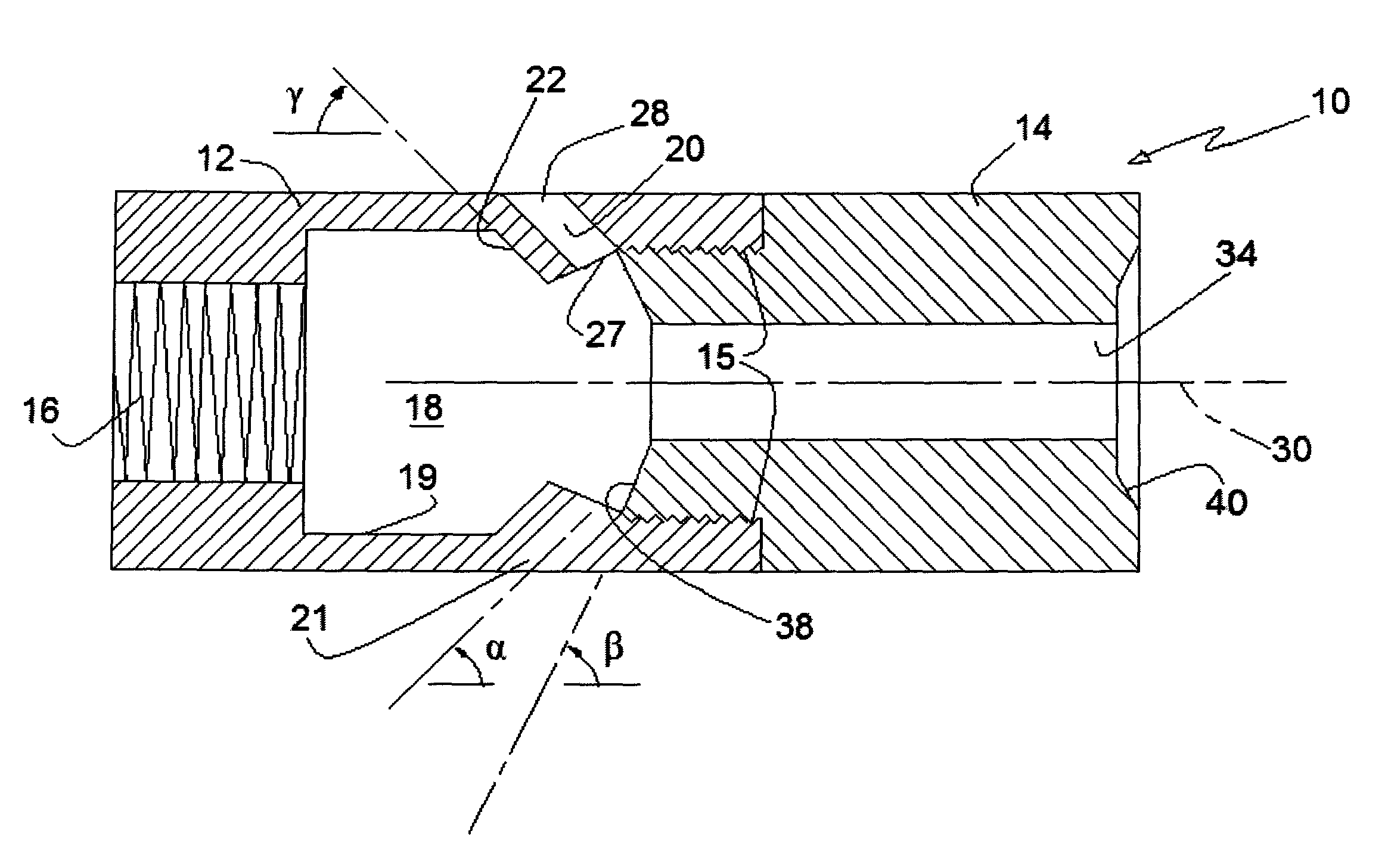
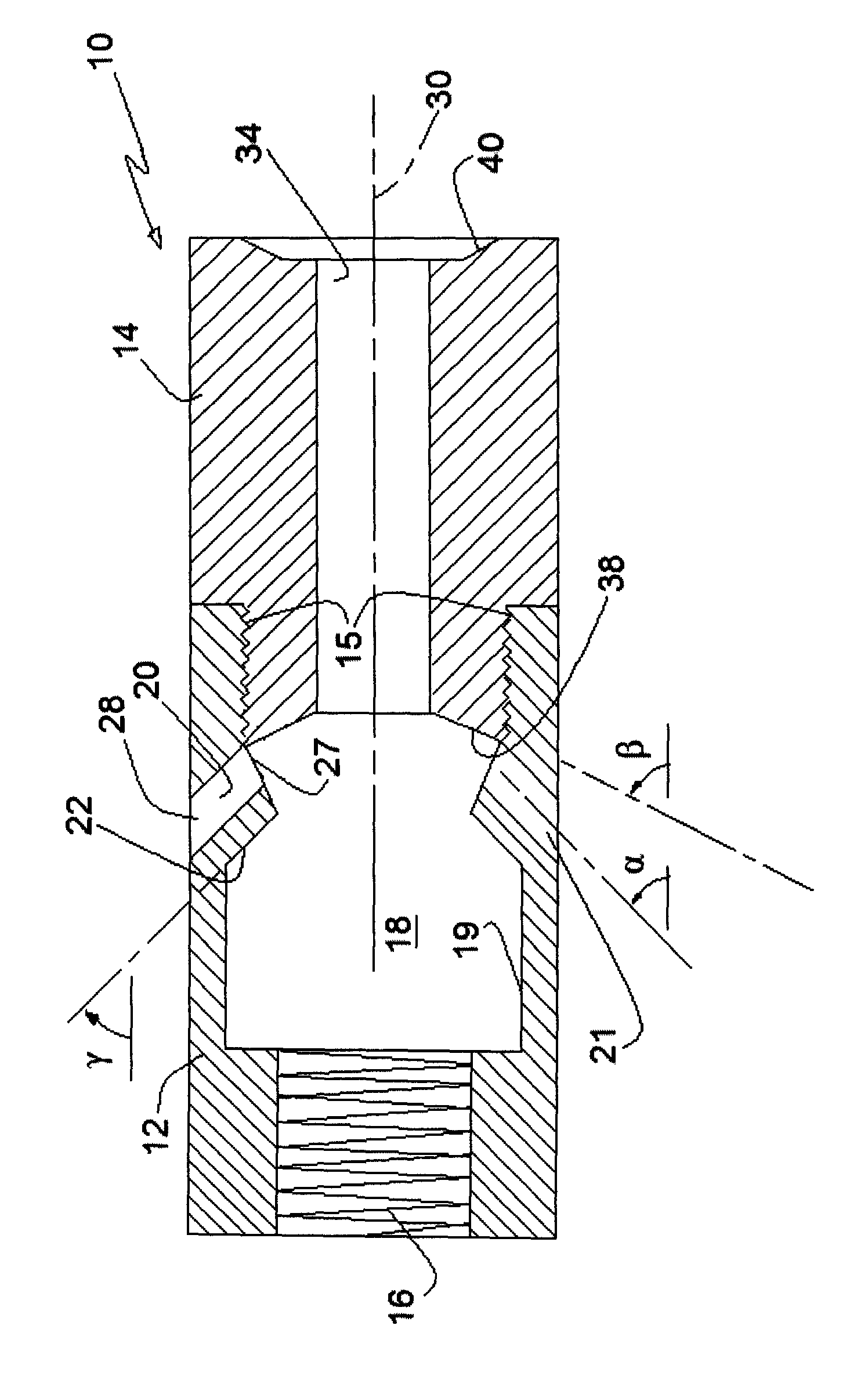
[0008]Referring to the drawing, the cross-section of a muzzle brake constructed in accordance with the teachings of the present invention is shown. For convenience in manufacture, the compensator or muzzle brake 10 is constructed in a first section 12 and a second section 14 that may be threadedly engaged 15 to form a unitary cylindrical structure. The first section 12 is internally threaded 16 for attachment to the barrel of a firearm. The cylindrical structure forming the muzzle brake 10 will normally be secured to the barrel of a firearm having the muzzle portion of the barrel externally threaded to accept the internal threading 16 of the muzzle brake. The muzzle brake thus forms a cylindrical accessory or attachment to the barrel of the firearm. The first section also includes an expansion chamber 18 wherein expanding gases following a projectile enters and subsequently escapes through strategically positioned ports. Ports 20, 21 communicate with the expansion chamber and permit...


PUM


Abstract

A muzzle brake/compensator for attachment to the barrel of a firearm incorporates an expansion chamber for receiving expanding gases following a projectile exiting from the barrel of the firearm. The expanding gases in the expansion chamber are directed to strategically positioned ports in the periphery of the muzzle brake which directs the escaping expanding gases radially outwardly from the centerline of the firearm bore and inclined toward the firearm/shooter. The expansion chamber is provided with a baffle surface extending from the interior surface of a bore extension or wiper section to the port entrances of the respective ports. The angle of the baffle surface with respect to the bore centerline is limited to a range within which significant reduction in recoil force is achieved.

Description

FIELD OF THE INVENTION[0001]The present invention is directed to devices to reduce recoil of a firearm when discharged, resulting from gas production, gas pressure increase, gas and projectile acceleration, and escaping high pressure gas when a firearm is discharged.BACKGROUND OF THE INVENTION[0002]The acceleration of a projectile in the barrel of a rifle, shotgun or handgun results in a reaction force, or recoil, imparted to the weapon and ultimately to the shooter. As the projectile is accelerated along the barrel and exits the muzzle of the weapon, high pressure gases escaping behind the projectile contribute to the recoil force. It is well known in the prior art to redirect these expanding gases as the projectile nears the muzzle; the direction of these redirected gases is generally inclined toward the weapon / shooter thus resulting in a counter-recoil force. It is well known that the reduction in recoil force may render the discharging of the firearm more pleasant for the shoote...

Claims


Application Information

Patent Timeline
IPC IPC(8): F41A21/28
CPCF41A21/36F41A21/28
Inventor ECKEL, DON, M.
Owner ECKEL DON M
Why Eureka
Try Eureka