Switchgear assembly with a contact gap

a technology of contact gap and switchgear, which is applied in the direction of air-break switch, high-tension/heavy-dress switch, electrical apparatus, etc., can solve the problem of reducing flow speed, and achieve the effect of filling and emptying hot gas spa

Active Publication Date: 2014-01-21
SIEMENS ENERGY GLOBAL GMBH & CO KG
View PDF22 Cites 4 Cited by
  • Summary
  • Abstract
  • Description
  • Claims
  • Application Information

AI Technical Summary

Benefits of technology

[0005]It is therefore the object of the invention to specify a switchgear assembly which enables an effective filling and emptying of the hot gas space with switching gas within short time intervals.

Problems solved by technology

When switching gas flows within a deflector channel, there is a fear of the flow speed reducing due to the friction which occurs in the interior of the deflector channel.

Method used


Image

  • Switchgear assembly with a contact gap
  • Switchgear assembly with a contact gap
  • Switchgear assembly with a contact gap

Examples


third embodiment

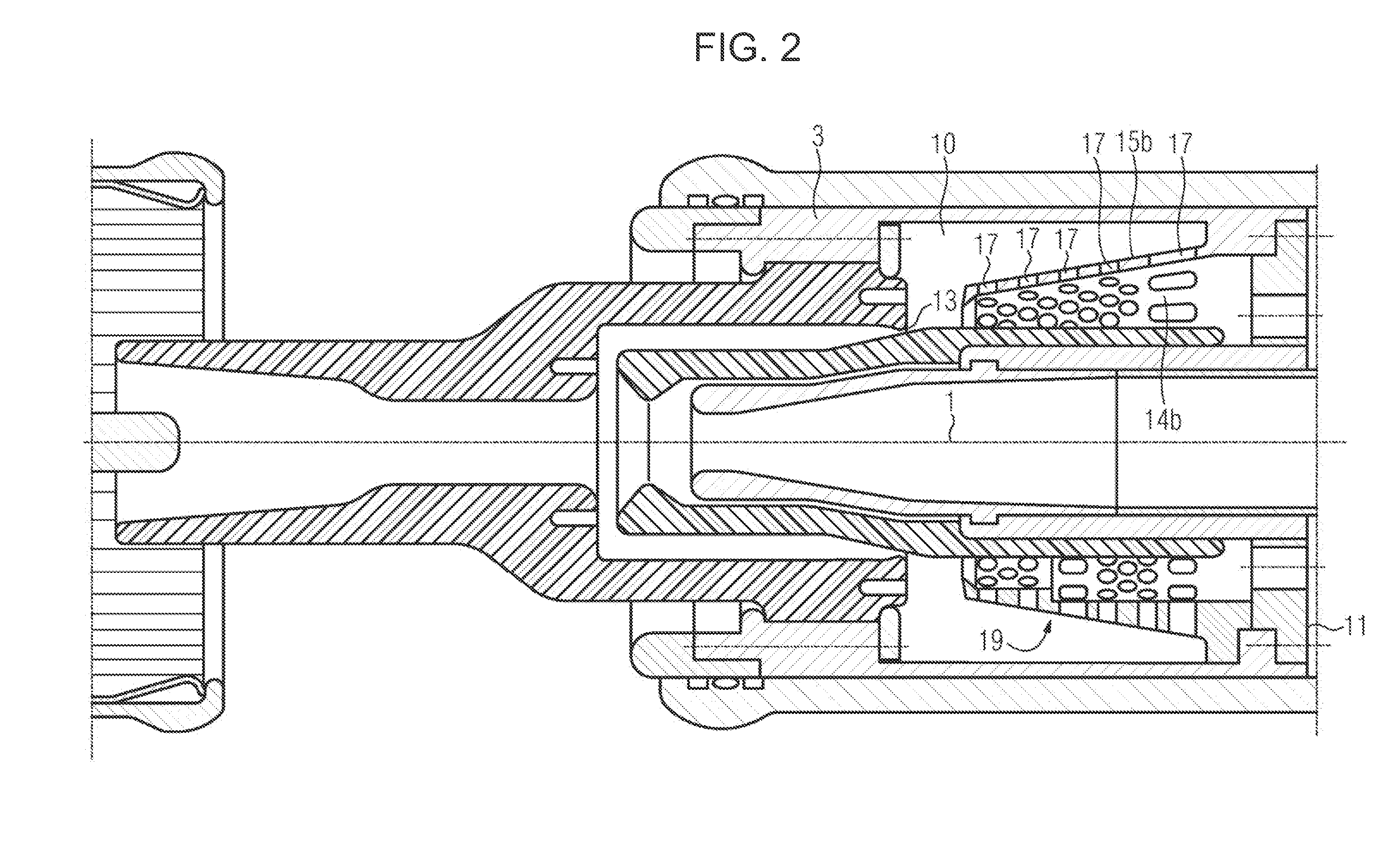
[0075]While the designs of the deflector element 15a, 15b according to FIGS. 1 and 2 are essentially provided in an electrically conducting material, in the third embodiment according to FIG. 3, a design of the deflector element 15c here is provided as an insulated part. At the same time, it can be provided that parts of the deflector element 15c according to FIG. 3 are equipped with metallic reinforcements. Likewise, it can also be provided that the deflector elements 15a, 15b according to FIGS. 1 and 2 respectively are at least partially provided with covers made from insulating material.

first embodiment

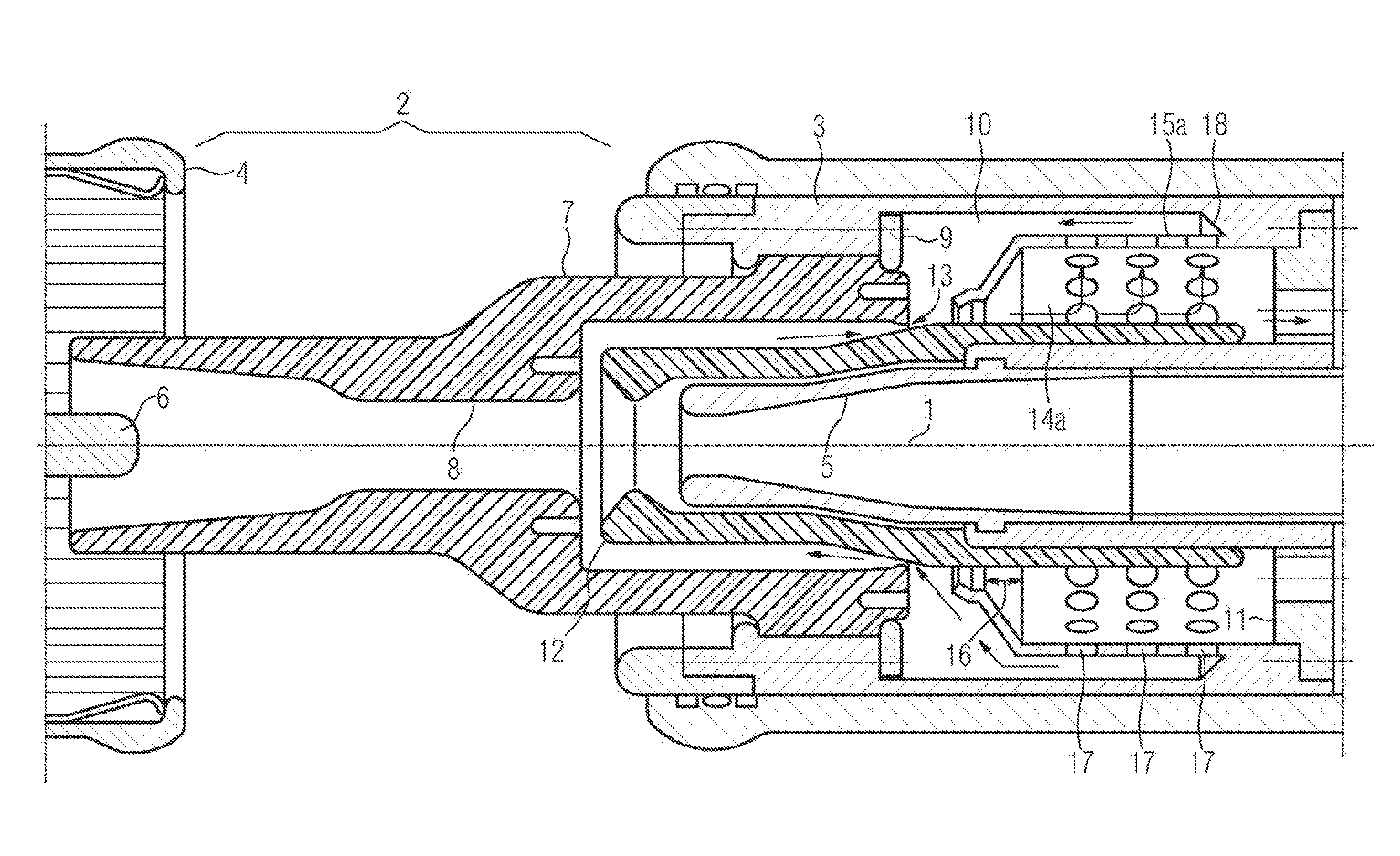
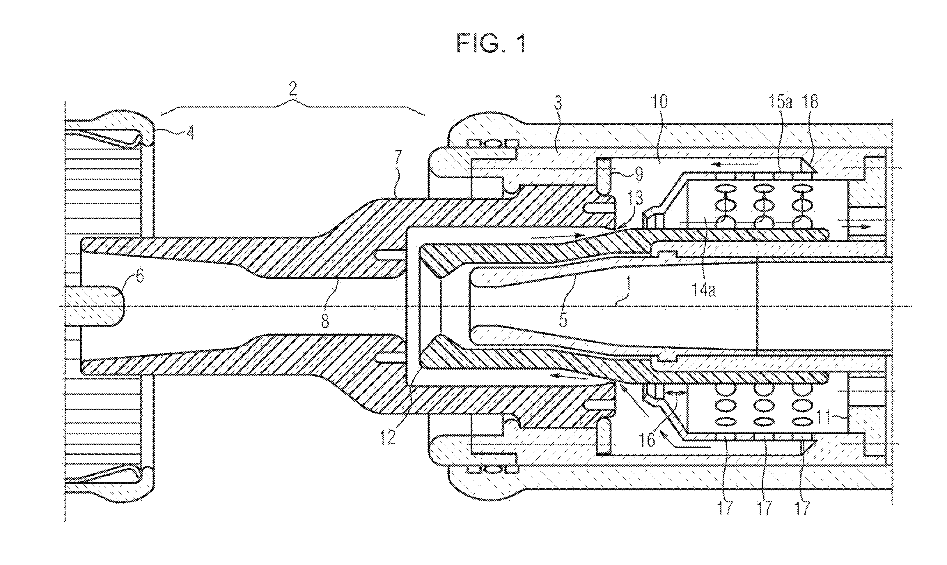
[0076]The third variant of a deflector element 15c according to FIG. 3 is designed sitting on the auxiliary nozzle 12. In the present case, a single-piece connection is provided between auxiliary nozzle 12 and deflector element 15c. An outer sleeve surface of the insulating material nozzle 12 passes completely through the deflector element 15c and therefore also the deflector channel 14c. It can also be provided that the insulating material nozzle 12 only extends partially into the deflector element 15c. The deflector channel 14c according to FIG. 3 encompassed by the deflector element 15c has a ring structure. At the same time, a continuous expansion of the deflector channel 14c is provided in the first embodiment above the longitudinal axis 1. Again, a projecting nose, which constitutes a taper in the form of a nozzle constriction directly in the region of the inlet opening, is provided in the region of the switching gas inlet opening of the deflector element 15c. The deflector el...

second embodiment

[0077]In the deflector element 15c shown below the longitudinal axis 1, it is provided that a sleeve surface in the shape of a truncated cone is provided on the outer sleeve side, while the inner sleeve side of the deflector element 15c, which borders the deflector channel 14c, is bordered by two abutting substantially hollow cylindrical sections, wherein a step-like expansion 19 occurs from the one section with the smaller cross section to the other section with the larger cross section. Struts for supporting the deflector element 15c are preferably to be arranged in the region of the step between the two hollow cylindrical sections of the deflector channel 14c.

[0078]Unlike the designs shown in FIGS. 1 and 2, a space is provided from the face wall of the hot gas space 10 at the end of the deflector channel 14c which faces away from the outlet opening 13.

[0079]Although the invention has been illustrated and described by means of the preferred embodiments, the invention is not restr...


PUM


Abstract

A switchgear assembly has a contact gap and an insulating material nozzle. The insulating material nozzle at least partly encloses the contact gap. A nozzle channel for the insulating material nozzle opens with a outlet opening in a hot gas space. A deflector element is disposed within the hot gas space which defines a deflector channel. The deflector channel has a segment which has an expanding cross-section in the stream direction of a switching gas in the hot gas space.

Description

BACKGROUND OF THE INVENTIONField of the Invention[0001]The invention relates to a switchgear assembly having an insulating material nozzle at least partially enclosing a contact gap with a nozzle channel which opens out into a hot gas space in which is arranged a deflector element with deflector channel, wherein extinguishing gas discharging from the nozzle channel in the discharge direction into the hot gas space is diverted into the deflector channel.[0002]A switchgear assembly of this kind is disclosed, for example, in the patent abstract of Japan JP 02-086023. This describes a switchgear assembly which has a hot gas space. A nozzle channel of an insulating material nozzle opens out into the hot gas space. A deflector element with deflector channel is arranged in the hot gas space in order to divert and guide gas flows in the hot gas space. Switching gas discharging from the nozzle channel is fed into the deflector channel of the deflector element. In doing so however, due to the...

Claims


Application Information

Patent Timeline
Patent Type & Authority Patents(United States)
IPC IPC(8): H01H33/88
CPCH01H33/74H01H33/901H01H33/703H01H2033/888H01H33/70H01H33/90
Inventor CERNAT, RADU-MARIANDIENEMANN, HOLDGIERE, STEFANLEHMANN, VOLKERMEINHERZ, MANFRED
Owner SIEMENS ENERGY GLOBAL GMBH & CO KG
Why Eureka
Try Eureka