Device and method for applying a vibration signal to a human skull bone

a technology of vibration signal and skull bone, applied in the field of devices and methods for applying vibration signal to human skull bones, can solve the problems of insufficient coupling, lack of desired precision of correlation between the output of the accelerometer and the vibrational force applied to the skull bon

Active Publication Date: 2014-01-21
OTICON MEDICAL
View PDF5 Cites 1 Cited by
  • Summary
  • Abstract
  • Description
  • Claims
  • Application Information

AI Technical Summary

Benefits of technology

[0013]As used herein, the singular forms “a”, “an”, and “the” are intended to include the plural forms as well (i.e. to have the meaning “at least one”), unless expressly stated otherwise. It will be further understood that the terms “has”, “includes”, “comprises”, “having”, “including” and / or “comprising”, when used in this specification, specify the presence of stated features, integers, steps, operations, elements and / or components, but do not preclude the presence or addition of one or more other features, integers, steps, operations, elements, components and / or groups thereof. It will be understood that when an element is referred to as being “connected” or “coupled” to another element, it can be directly connected or coupled to the other element, or intervening elements may be present, unless expressly stated otherwise. As used herein, the term “and / or” includes any and all combinations of one or more of the associated listed items. The steps of any method disclosed herein do not have to be performed in the exact order disclosed, unless expressly stated otherwise.

Problems solved by technology

Since, however, the mechanical impedance, or admittance, of the coupling is not well known and further may change, e.g. due to aging of the used materials and / or the person's tissue and bone structure, the correlation between the output of the accelerometer and the vibrational force applied to the skull lacks the desired precision.

Method used


Image

  • Device and method for applying a vibration signal to a human skull bone
  • Device and method for applying a vibration signal to a human skull bone
  • Device and method for applying a vibration signal to a human skull bone

Examples


Embodiment Construction

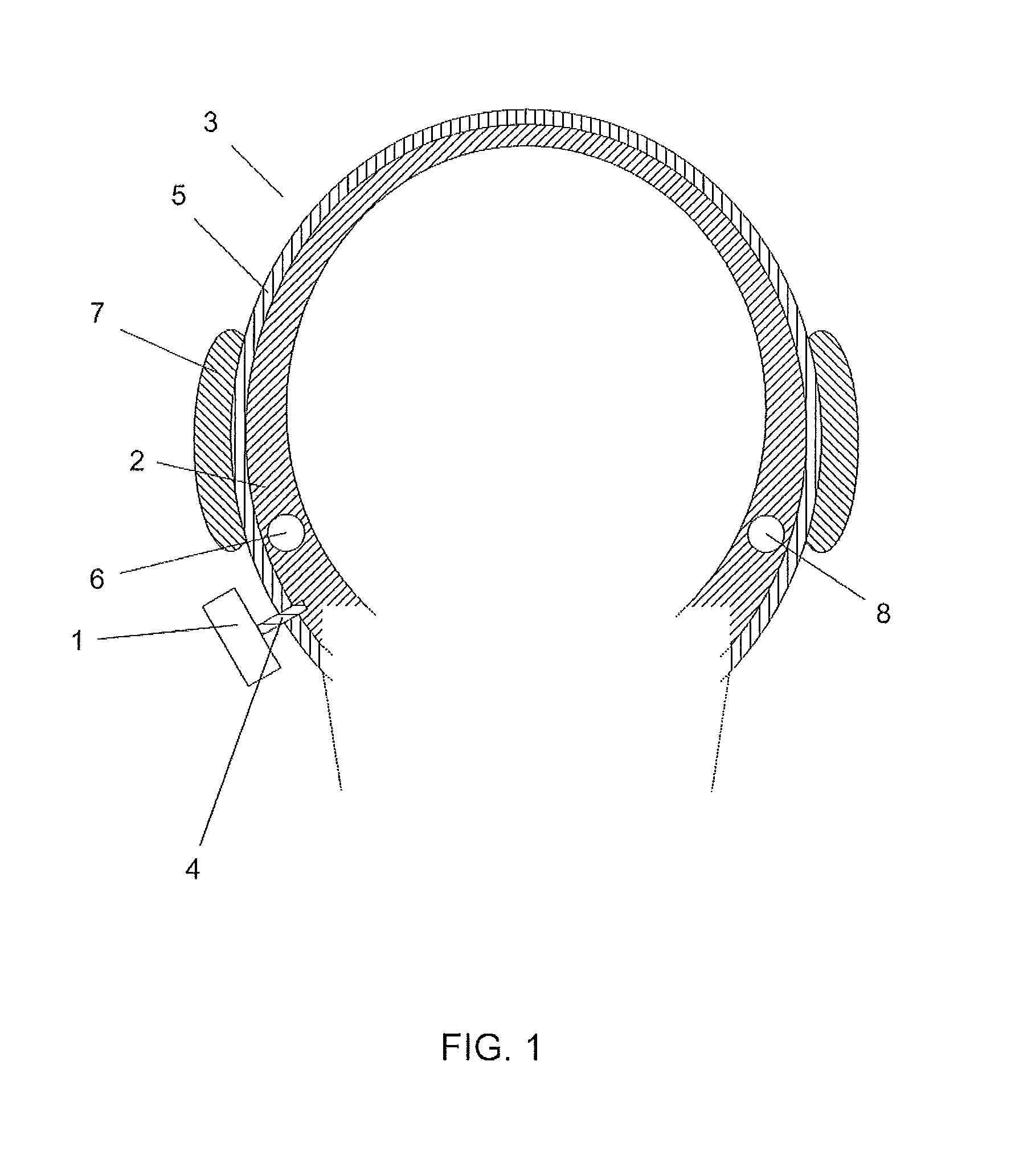
[0022]FIG. 1 shows a vibrator 1 connected to the skull bone 2 of a person's head 3 via a fixture 4 osseointegrated in the skull bone 2. The fixture 4 protrudes through the tissue 5 and the skin covering the skull 2. Vibrations generated in the vibrator 1 travel through the fixture 4 to the skull bone 2 and further on to the proximal inner ear 6. This enables the person to perceive the vibrations as sound, even in the case that the outer ear 7 or the middle ear (not shown) has a deficiency that causes acoustic signals to be attenuated, provided that the vibrations are strong enough. The vibrations also travel to the distal inner ear 8, which further enables the person to perceive the vibrations as sound in the case that the person is completely deaf on the proximal inner ear 6, again provided that the vibrations are strong enough.

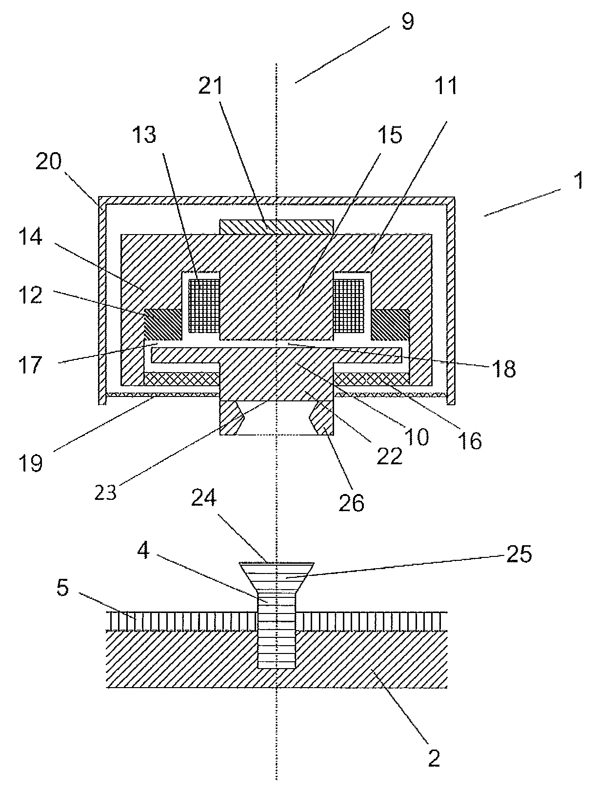
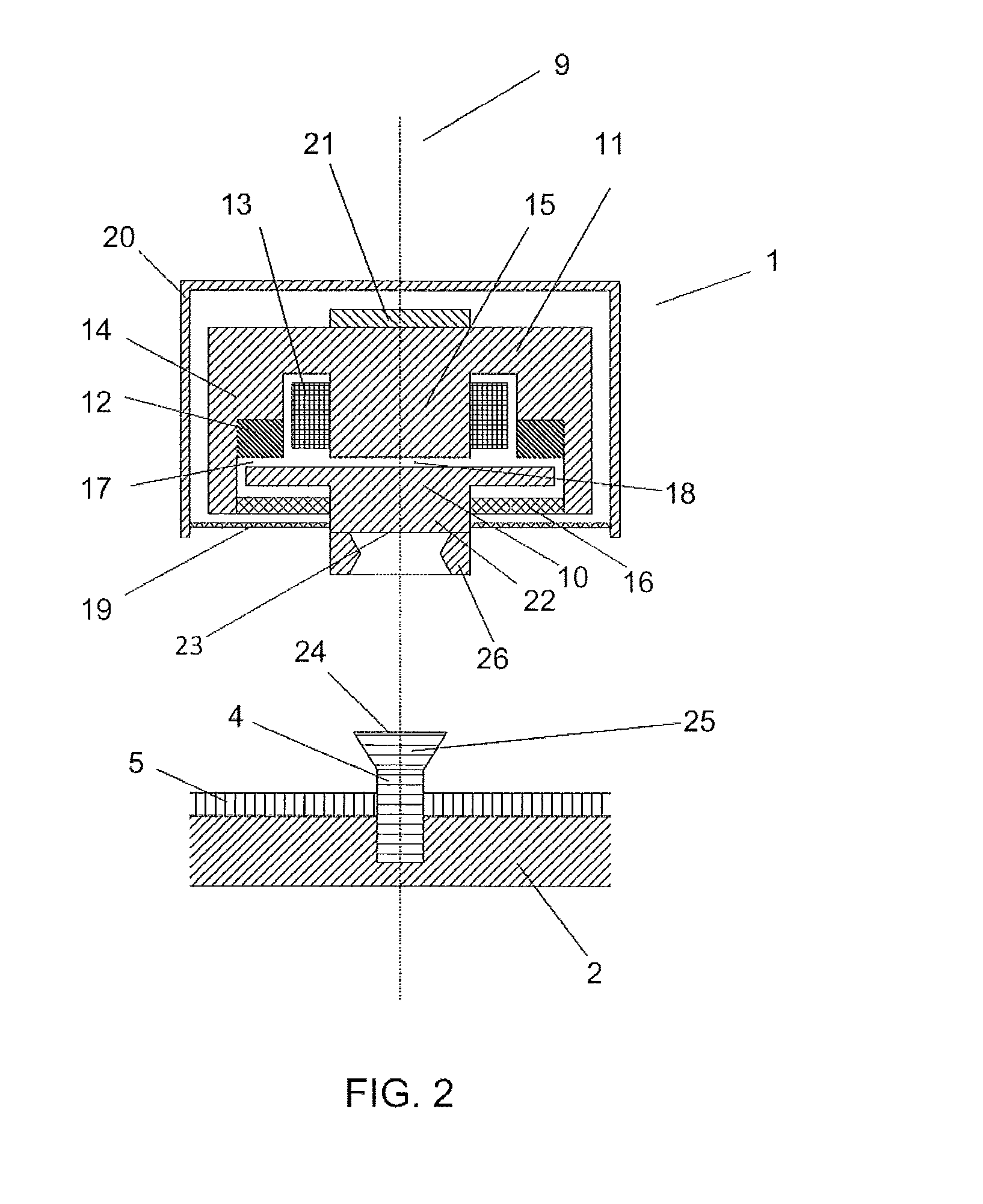
[0023]The vibrator 1 shown in the upper part of FIG. 2 is substantially rotationally symmetric with respect to the line 9 and comprises a vibration element ...


PUM


Abstract

Hearing losses caused by deficiencies in a person's outer or middle ear may be compensated for by converting received sounds to vibrations and transmitting the vibrations to the skull bone (2). Bone-conduction hearing devices (27) may transmit such vibrations transcutaneously or percutaneously. In both cases, a precise determination of the magnitude of the vibrations applied to the skull bone (2) is needed for determining the person's bone-conduction hearing thresholds as well as for calibrating the hearing devices (27). The present invention provides a device (1, 27, 37) and a method, which allow determination of the applied vibrational force with better precision than prior art devices and methods. This is achieved by placing an accelerometer (21) on the countermass (11) of the vibrator (1) that generates the vibration signal. The accelerometer (21) thus provides an acceleration signal representative of an acceleration of the countermass (11), from which acceleration signal the vibrational force may be determined precisely and reproducibly.

Description

CROSS REFERENCE TO RELATED APPLICATIONS[0001]This non provisional application claims the benefit Under 35 U.S.C. §119(e) to U.S. Provisional Application No. 61 / 351,955 filed on Jun. 7, 2010 and Under 35 U.S.C. §119(a) to Patent Application No. 10165090.1, filed on Jun. 7, 2010 in the European Patent Office. The entire contents of all of the above applications is hereby incorporated by reference into the Present application.TECHNICAL FIELD[0002]The present invention relates to a device and a method for applying a vibration signal to a human skull bone. More specifically, the present invention relates to such a device and such a method, which allow for determining the applied vibrational force.[0003]The invention may e.g. be useful in applications such as determining bone-conduction hearing thresholds as well as calibrating and / or operating bone-conduction hearing devices.BACKGROUND ART[0004]It is well known in the art to compensate for hearing losses mainly caused by deficiencies in ...

Claims


Application Information

Patent Timeline
Patent Type & Authority Patents(United States)
IPC IPC(8): H04R25/00
CPCH04R2460/13H04R25/606
Inventor BERN, BENGT
Owner OTICON MEDICAL
Why Eureka
Try Eureka