Robot cleaner system having robot cleaner and docking station

a robot cleaner and robot technology, applied in the direction of vacuum cleaners, floor sweeping machines, cleaning filter means, etc., can solve the problems of leaking dust from the robot cleaner into the docking station to be leaked again into the room, complicating the configuration of the dust-removal device, etc., to achieve the effect of improving the docking structur

Inactive Publication Date: 2014-01-28
SAMSUNG ELECTRONICS CO LTD
View PDF6 Cites 28 Cited by
  • Summary
  • Abstract
  • Description
  • Claims
  • Application Information

AI Technical Summary

Benefits of technology

The invention is about a robot cleaner system with a better way to connect to a docking station. This allows the robot cleaner to make better contact with the docking station, which means it can vacuum more efficiently. No extra equipment is needed to make this connection.

Problems solved by technology

This, however, has a problem of the great loss of a suction force generated from the suction unit or causing the dust being moved from the robot cleaner into the docking station to be leaked again into a room.
However, to move the connector, it is necessary to provide a drive device for the connector within the dust-removal device, and this has a problem of complicating the configuration of the dust-removal device.

Method used


Image

  • Robot cleaner system having robot cleaner and docking station
  • Robot cleaner system having robot cleaner and docking station
  • Robot cleaner system having robot cleaner and docking station

Examples


first embodiment

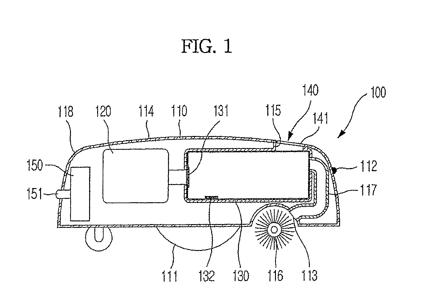
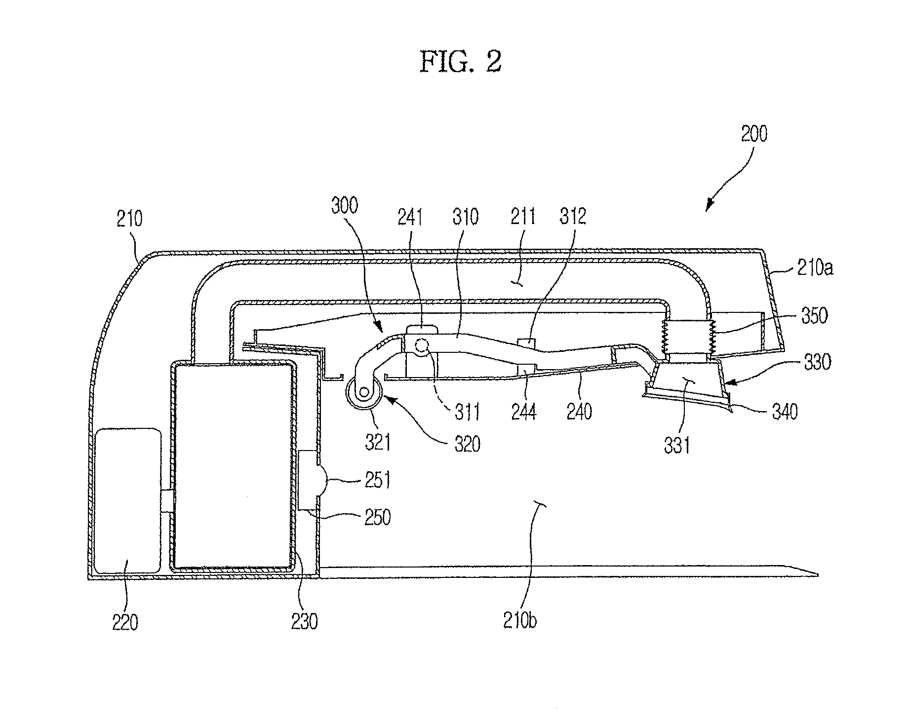
[0037]FIGS. 1 and 2 are sectional views, respectively, showing a robot cleaner and a docking station of a robot cleaner system according to the present invention.

[0038]As shown in FIGS. 1 and 2, the robot cleaner system according to the present invention includes a robot cleaner 100 and a docking station 200. The robot cleaner 100 performs a cleaning operation for a cleaning region by self-running thereof, and returns to the docking station 200 if dust over a predetermined level is accumulated therein, to discharge the dust.

[0039]As shown in FIG. 1, the robot cleaner 100 includes a robot body 110, and a first suction device 120 and a first dust-collecting device 130 installed in the robot body 110.

[0040]The first suction device 120 is used to generate a suction force required to suction dust. The first suction device 120 includes a suction motor (not shown) and a blowing fan (not shown). The first dust-collecting device 130 is used to collect and store the dust introduced into the r...

second embodiment

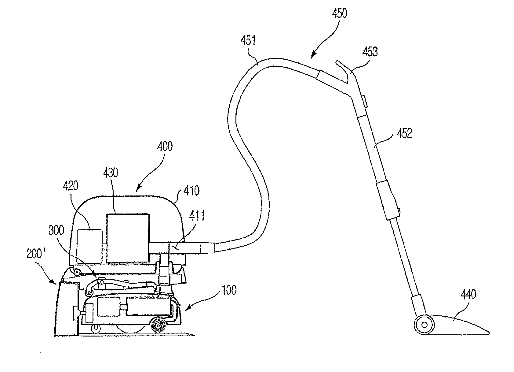
[0067]FIG. 6 is a sectional view illustrating the configuration of a robot cleaner system according to the present invention. FIG. 7 is a sectional view showing a partial configuration of FIG. 6. In the present embodiment, a vacuum cleaner is connected to the docking station, to suction dust in the robot cleaner. In the following description, the same reference numerals will be used to refer to the same elements as those of the embodiment shown in FIGS. 1 to 5, and only characteristic items of the present embodiment will be described.

[0068]As shown in FIGS. 6 and 7, the robot cleaner system according to the present embodiment includes a vacuum cleaner 400 to be connected to a docking station 200′. The vacuum cleaner 400 is used to suction dust collected in the robot cleaner 100 when the robot cleaner 100 docks with the docking station 200′.

[0069]The vacuum cleaner 400 is separable from the docking station 200′. Accordingly, a user can clean the floor by using the separated vacuum cl...


PUM


Abstract

A robot cleaner system includes docking structure to allow a dust discharge port of a robot cleaner to come into close contact with a dust suction port of a docking station without an additional drive device. The robot cleaner system includes a robot cleaner having a dust discharge port, a docking station having a dust suction port to suction dust collected in the robot cleaner, and a docking device to perform a seesaw movement as it contacts the robot cleaner when the robot cleaner docks with the docking station, to allow the dust suction port to come into close contact with the dust discharge port. The docking device includes a link member installed in the docking station in a pivotally rotatable manner, one end having a contact portion to come into contact with the robot cleaner, and the other end having a docking portion defining the dust suction port therein.

Description

CROSS-REFERENCE TO RELATED APPLICATION[0001]This application is a Divisional application of application Ser. No. 12 / 149,375 filed Apr. 30, 2008, now pending, and is based upon and claims the benefit of priority from the prior Korean Patent Application No. 2007-0085304, filed on Aug. 24, 2007, the entire contents of both of which are incorporated herein by reference.BACKGROUND OF THE INVENTION[0002]1. Field of the Invention[0003]The present invention relates to a robot cleaner system, and, more particularly, to a robot cleaner system having a docking station installed to suction and remove dust collected in a robot cleaner.[0004]2. Description of the Related Art[0005]A cleaner is an appliance to get rid of dirt and clean a room. Generally used is a vacuum cleaner to suction dirt by use of a suction force generated from a low-pressure unit. Recently, the development of a robot cleaner is underway. The robot cleaner get rids of dirt from the floor by a self-running function thereof wit...

Claims


Application Information

Patent Timeline
Patent Type & Authority Patents(United States)
IPC IPC(8): A47L9/10
CPCA47L2201/024A47L9/20A47L2201/00A47L9/28A47L9/00A47L11/24
Inventor LEE, YOUN BAEKYANG, SOO SANGOH, YEON TAEKKIM, JEONG HUN
Owner SAMSUNG ELECTRONICS CO LTD
Why Eureka
Try Eureka