Dynamic cervical plate

a cervical plate and cervical plate technology, applied in the field of spinal plate, can solve the problems of degenerative disc disease, disc deterioration or weakening, and chronic pain, and achieve the effect of reducing the risk of fracture, and improving the quality of li

Active Publication Date: 2014-01-28
K2M
View PDF38 Cites 23 Cited by
  • Summary
  • Abstract
  • Description
  • Claims
  • Application Information

AI Technical Summary

Problems solved by technology

For many reasons, such as aging and trauma, the intervertebral discs can begin to deteriorate and weaken, potentially resulting in chronic pain, degenerative disc disease, or even tearing of the disc.
Ultimately, the disc may deteriorate or weaken to the point of tearing and herniation, in which the inner portions of the disc protrude through the tear.
A herniated disc may press against, or pinch, the spinal nerves, thereby causing radiating pain, numbness, tingling, and / or diminished strength or range of motion.
However, should the prosthetic protrude from between the adjacent vertebrae and thereby contact the surrounding nerves or tissues, the patient may experience additional discomfort.
Fixed cervical plates resist this change due to their fixed axial length, which may eventually stress the spine and cause pain or discomfort.
However, the known adjustable plates require subsequent surgical procedures to adjust the axial dimension of the plate.

Method used


Image

  • Dynamic cervical plate
  • Dynamic cervical plate
  • Dynamic cervical plate

Examples


Embodiment Construction

[0052]Particular embodiments of the present disclosure will be described herein with reference to the accompanying drawings. As shown in the drawings and as described throughout the following description, and as is traditional when referring to relative positioning on an object, the term “proximal” refers to the end of the apparatus that is closer to the user and the term “distal” refers to the end of the apparatus that is further from the user. In the following description, well-known functions or constructions are not described in detail to avoid obscuring the present disclosure with unnecessary detail.

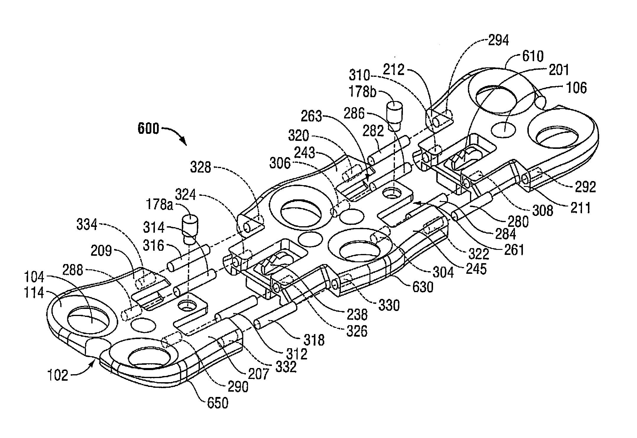
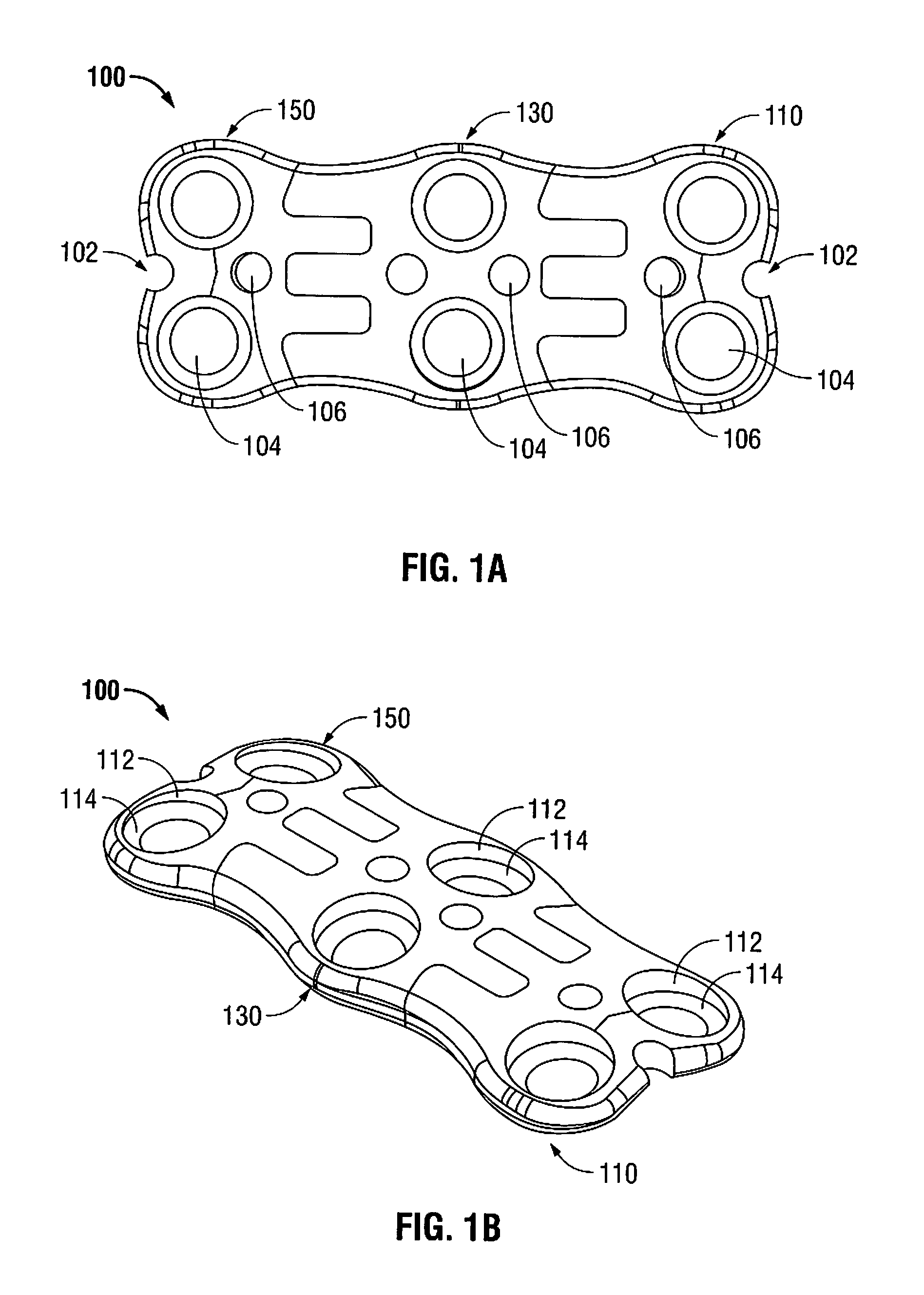
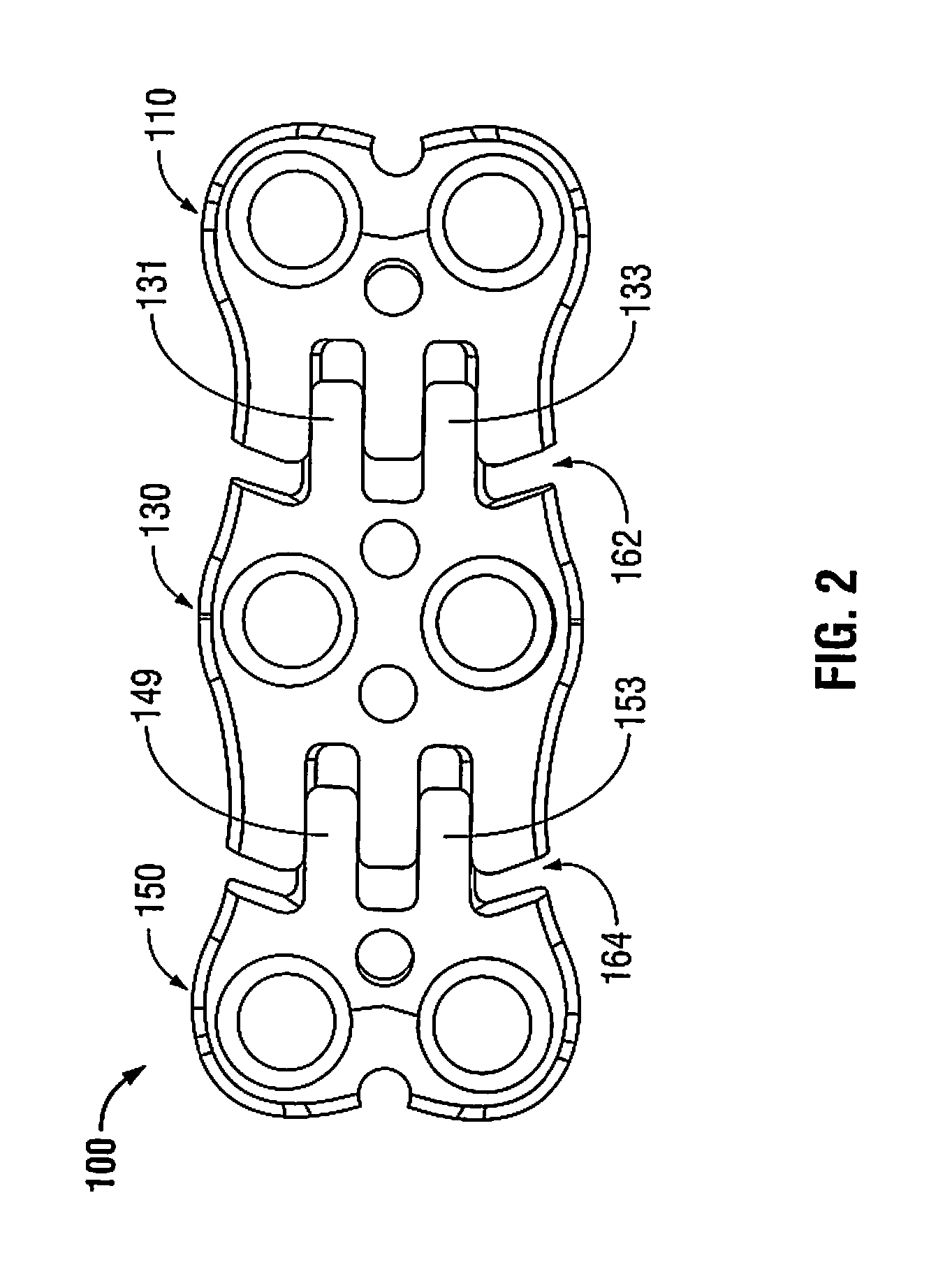
[0053]Referring now to the drawings, in which like reference numerals identify identical or substantially similar parts throughout the several views, FIGS. 1A-1B illustrate a dynamic cervical plate that is generally designated as 100. The dynamic cervical plate 100 includes a first end section 110, a middle section 130, and a second end section 150. As shown in FIGS. 1A and 1B, the ...


PUM


Abstract

A dynamic cervical plate includes a first end section and a second end section. In embodiments, the dynamic cervical plate may include one or more middle sections positioned between the first and second end sections. Each section may be longitudinally repositionable. Each section may include a plurality of openings for receiving threaded fasteners such as a self-starting screw or a self-tapping screw. In addition, each section may include an orifice for releasably mating with a drill guide. Each of the end sections may include a notch at one end for aligning with the drill guide or fixation pins. In one embodiment, a pin is used to interconnect the sections. In other embodiments, support bars are used to limit flexure between sections. In embodiments, one or more locking elements and / or one or more support bars may operably interconnect each section.

Description

CROSS-REFERENCE TO RELATED APPLICATIONS[0001]This application is a continuation-in-part of International Application No. PCT / US08 / 80897, filed on Oct. 23, 2008, which claims the benefit of and priority to U.S. Provisional Patent Application Ser. No. 61 / 000,070, filed Oct. 23, 2007, and U.S. Provisional Patent Application Ser. No. 61 / 280,796, filed on Nov. 9, 2009, the entire contents of each of the prior applications are incorporated by reference herein.BACKGROUND[0002]1. Technical Field[0003]The present disclosure relates generally to a spinal plate and, more particularly, to a dynamic cervical plate.[0004]2. Background of Related Art[0005]The human spinal column is a highly complex structure. It includes more than twenty discrete bones, known as vertebrae, coupled sequentially to one another to house and protect critical elements of the nervous system. The cervical portion of the spine, which comprises the top of the spine up to the base of the skull, includes the first seven vert...

Claims


Application Information

Patent Timeline
Patent Type & Authority Patents(United States)
IPC IPC(8): A61B17/56A61F2/30A61B17/80A61B17/58
CPCA61B17/1728A61B17/7059A61B17/8009A61B17/8023A61B17/8057A61B17/1757A61B17/7058A61B17/8635
Inventor MCCLINTOCK, LARRYWALLENSTEIN, TODDHARRIS, PETERSTRAUSS, KEVIN R.CARNES, MEGAN
Owner K2M
Why Eureka
Try Eureka