
Embolic implant and method of use

a technology of embolism and implants, applied in the field of embolism devices, can solve the problems of immediate occlusion of the cerebral artery, devices may also be deposited,

Active Publication Date: 2014-02-04
COVIDIEN LP
View PDF10 Cites 48 Cited by
  • Summary
  • Abstract
  • Description
  • Claims
  • Application Information

AI Technical Summary

Problems solved by technology

The devices may also be deposited in aneurysms.
Expansion of the cage like structure, and concurrent expansion of the membrane, results in immediate occlusion of the cerebral artery.

Method used


Image

  • Embolic implant and method of use
  • Embolic implant and method of use
  • Embolic implant and method of use

Examples


Embodiment Construction

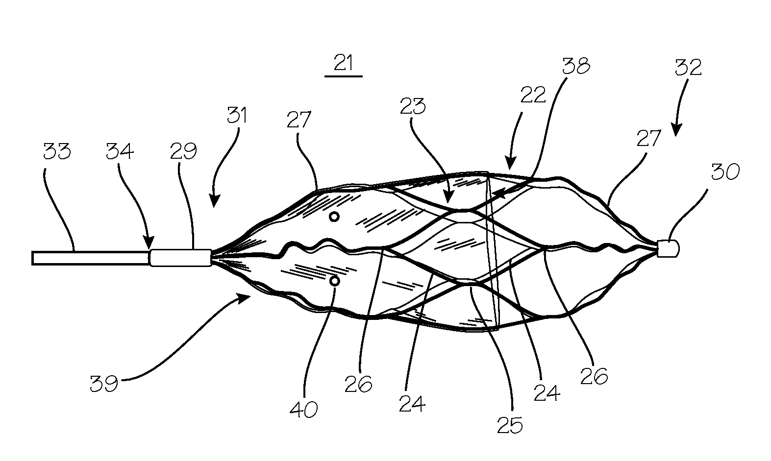
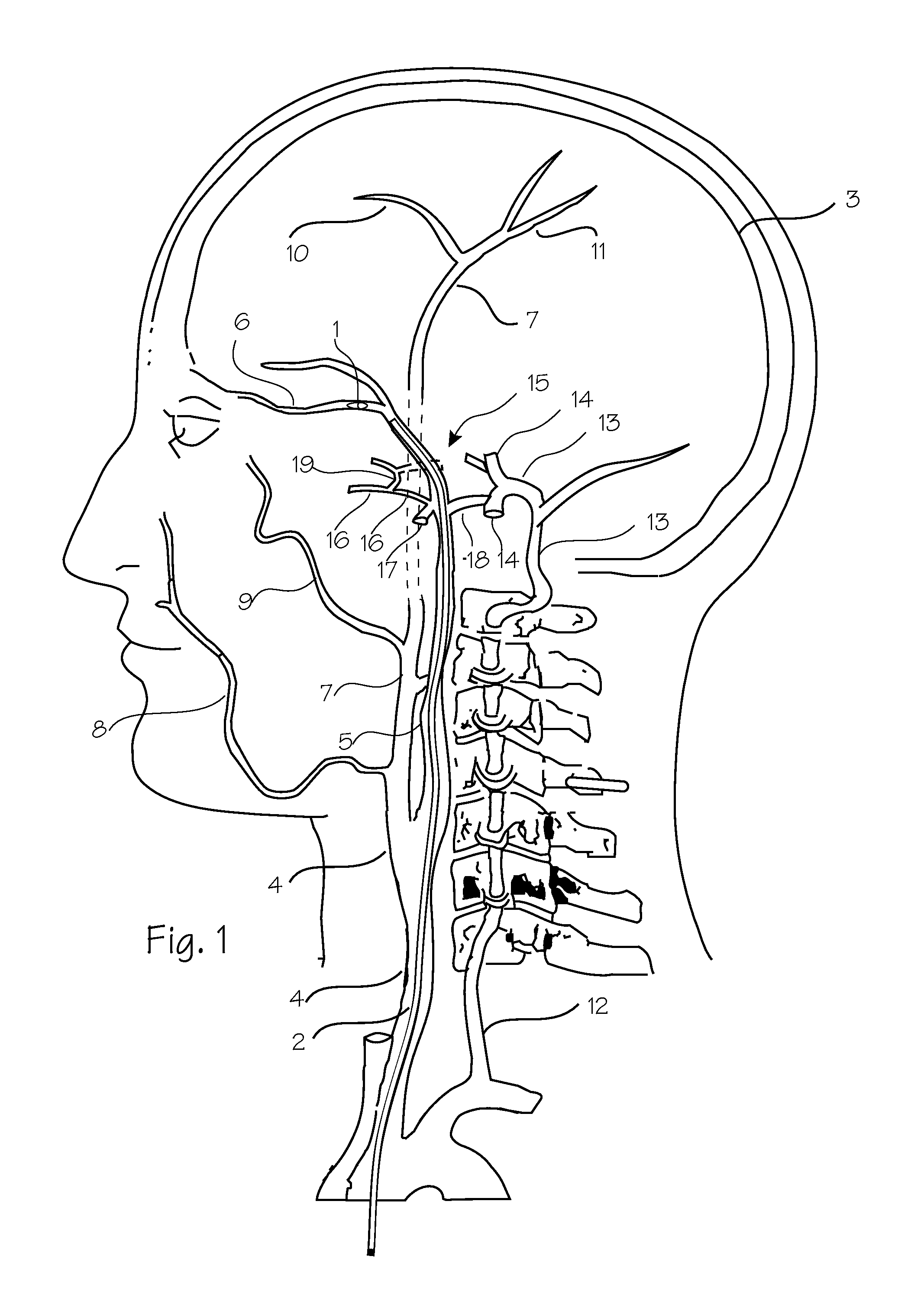
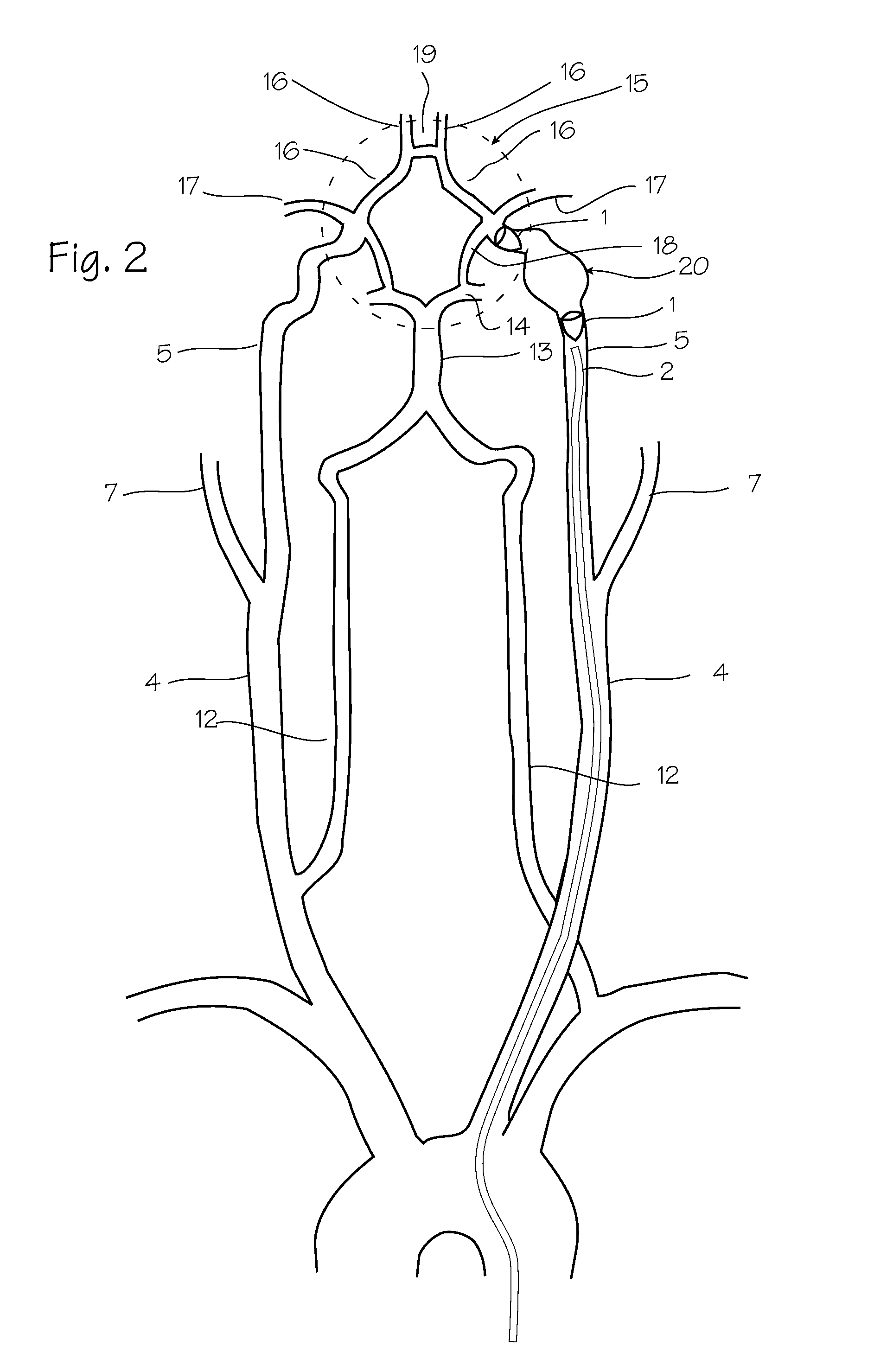
[0039]FIGS. 1 and 2 show the vasculature of the brain in sufficient detail to illustrate the use of the embolic implants shown in the following illustrations. The embolic implant 1 is shown in an exemplary placement. The embolic implant is delivered to this site of a vascular defect with the delivery catheter 2. The neuro-vasculature, which is the intended environment of use for the embolic implant, supplies the brain 3 with blood through the carotid and the vertebral arteries on each side of the neck. The important arteries include the common carotid artery 4 in the neck, which will be the most common access pathway for the embolic implants, and the internal carotid artery 5 which supplies the opthalmic artery 6. The external carotid 7 supplies the maxillary artery 8, the middle meningeal artery 9, and the superficial temporal arteries 10 (frontal) and 11 (parietal). The vertebral artery 12 supplies the basilar artery 13 and the cerebral arteries including the posterior cerebral ar...


PUM

PropertyMeasurementUnit
diameteraaaaaaaaaa
diameteraaaaaaaaaa
diameteraaaaaaaaaa

Abstract

A parent artery occlusion (PAO) device which provides for immediate occlusion of a cerebral artery to isolate a defect. The PAO device includes a self-expanding wire-frame prolate structure which is partially covered with an ePTFE membrane.

Description

[0001]This application claims priority to U.S. Provisional Application 61 / 493,108, filed Jun. 3, 2011.FIELD OF THE INVENTIONS[0002]The inventions described below relate to the embolic devices for use in neuro-vasculature (cerebral arteries and veins).BACKGROUND OF THE INVENTIONS[0003]The devices described below are intended for treatment of defects in the cerebral arteries and veins. Defects of the cerebral arteries include aneurysms, fusiform aneurysms, arteriovenous malformations, arteriovenous fistulas, cavernous fistulas and dissections and other hyper-vascular lesions (head and neck tumors, etc.). These defects cause of variety of symptoms, ranging from headache and vision loss to stroke and death. Preferably, these defects would be treated with devices and techniques that leave the associated parent artery or vein intact and patent so that it may continue to supply blood to regions of the brain which it naturally supplies. Such techniques include filling an aneurysm with occlu...

Claims


Application Information

Patent Timeline
Patent Type & Authority Patents(United States)
IPC IPC(8): A61F2/02
CPCA61L2400/16A61B2017/12095A61B2017/00876A61B2017/00526A61B17/12109A61F2/91A61F2230/0071A61F2220/0058A61L31/146A61B17/12172A61L2400/14A61B2017/00557A61B2017/12054A61B2017/12077A61B2017/12068A61L31/10A61B2017/00539A61L31/022A61B2017/12063A61B2017/00544A61L2430/36A61B2017/12086A61F2002/823A61F2230/0076A61F2/01A61L2420/04A61L2400/04A61B17/12031A61B2017/12081A61B2017/00867A61B17/12036C08L27/18A61B17/12113A61B17/12145A61B17/12154
Inventor STRAUSS, BRIAN MICHAELVALKO, JEFFREY J.LENKER, JAY A.PECOR, ROBERT A.BARKER, PETERCASTANEDA, MARICRUZ
Owner COVIDIEN LP
Learn More